LSM-1.2/16-W3-C Murata Power Solutions Inc, LSM-1.2/16-W3-C Datasheet - Page 2
LSM-1.2/16-W3-C
Manufacturer Part Number
LSM-1.2/16-W3-C
Description
DC/DC SM 16A W3-1.2V Non-Iso
Manufacturer
Murata Power Solutions Inc
Series
LSMr
Datasheet
1.LSM-0.7516-W3-C.pdf
(12 pages)
Specifications of LSM-1.2/16-W3-C
Product
Non-Isolated / POL
Output Power
19 W
Input Voltage Range
3 V to 5.5 V
Number Of Outputs
1
Output Voltage (channel 1)
1.2 V
Output Current (channel 1)
16 A
Output Type
Low Voltage
Lead Free Status / Rohs Status
Lead free / RoHS Compliant


0.062
(1.57)
LSM-0.75/16-W3
LSM-1/16-W3
LSM-1.2/16-W3
LSM-1.5/16-W3
LSM-1.8/16-W3
LSM-2/16-W3
LSM-2.5/16-W3
LSM-3.3/16-W3
LSM-T/16-W3
Performance Specifications and Ordering Guide
Typical at T
are tested/specified with external 22μF tantalum input and output capacitors. These capacitors
are necessary to accommodate our test equipment and may not be required to achieve specified
performance in your applications. See I/O Filtering and Noise Reduction.
Ripple/Noise (R/N) is tested/specified over a 20MHz bandwidth and may be reduced with external
filtering. See I/O Filtering and Noise Reduction for details.
P A R T
Nominal Output Voltage:
Output
Configuration:
Model
0.75, 1, 1.2, 1.5, 1.8, 2, 2.5, 3.3
or 0.75-3.3 (T) Volts
L = Unipolar
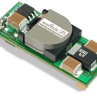
LSM WITH REMOVEABLE HEAT SHIELD
FOR HIGH TEMPERATURE SOLDER
A
Low Voltage
= +25°C under nominal line voltage and full-load conditions, unless noted. All models
N U M B E R
Non-Isolated SMT
2
DIMENSIONS IN INCHES (mm
(7.87)
0.310
0.049
(1.24)
0.112 TYP.
(2.84)
L SM
3
0.75-3.3
(Volts)
V
0.75
0.570 (14.48)
1.2
1.5
1.8
2.5
3.3
3 EQ. SP. @
0.190 (4.83)
OUT
1
2
(34.54)
BOTTOM VIEW
4
1.36
S T R U C T U R E
-
5
1.8
(Amps)
I
OUT
16
16
16
16
16
16
16
16
16
6
0.047
(1.19)
)
* Contact Murata-PS for availability.
/
(9.53)
0.375
16
1
R/N (mVp-p)
(1.32)
Typ.
0.052
-
30
30
30
30
30
30
30
30
30
(0.254)
0.010
Output
W3
Input Voltage Range:
Maximum Rated Output
Current in Amps
www.murata-ps.com
(13.97)
W3 = 3 to 5.5 Volts
0.55
(1.32)
0.052
Max.
CAUTION
PRESS TO REMOVE
THE HEAT SHIELD
AFTER THE SOLDER
PROCESS
RoHS-6 hazardous
substance compliant*
50
50
50
50
50
50
50
50
-
50
(5V nominal)
C
Refer to the last page for
Tape and Reel information.
Regulation (Max.)
±0.1%
±0.1%
±0.1%
±0.1%
±0.1%
±0.1%
±0.1%
±0.1%
(15.24)
±0.1%
Line
0.60
NOTCH IN SHELL
INDICATES PIN ONE
±0.25%
±0.25%
±0.25%
±0.25%
±0.25%
±0.25%
±0.25%
±0.25%
±0.25%
Load
Non-Isolated, Wide Input SMT DC/DC Converters
V
(Volts)
IN
5
5
5
5
5
5
5
5
Nom
5
M E C H A N I C A L
These devices have no minimum-load requirements and will regulate under no-load conditions.
Regulation specifications describe the output-voltage deviation as the line voltage or load is varied
from its nominal/midpoint value to either extreme.
Nominal line voltage, no-load/full-load conditions.
V
LSM-T/16-W3 specs are given with V
IN
= 4.5 Volts minimum for V
4.5-5.5
Input
Range
(Volts)
3-5.5
3-5.5
3-5.5
3-5.5
3-5.5
3-5.5
3-5.5
3-5.5
Pin
1
2
3
4
5
6
Technical enquiries email: sales@murata-ps.com, tel:
I/O Connections
50/11.12
50/11.12
On/Off Control
70/2.98
70/3.72
70/4.36
70/5.33
70/6.30
70/6.92
Function P63
(mA/A)
70/8.56
LSM-16A W3 Models
I
IN
V
OUT
Common
+Output
+Sense
+Input
OUT
S P E C I F I C A T I O N S
= 3.3 Volts.
Trim
OUT
Case C45
85.75%
89.5%
90.5%
91.5%
= 3.3 Volts, unless noted.
80%
84%
88%
93%
93%
Min.
V
Efficiency (Full Load)
IN
= nom.
Dimensions are in inches (mm shown for ref. only).
MDC_LSM-16A_W3.A04 Page 2 of 12
86.5%
88.8%
91.5%
92.5%
93.5%
Typ.
82%
86%
95%
95%
Components are shown for reference only.
Tolerances (unless otherwise specified):
.XX ± 0.02 (0.5)
.XXX ± 0.010 (0.25)
Angles ± 2˚
V
Third Angle Projection
IN
Typ.
81.5%
86.5%
88.0%
90.0%
92.5%
95.5%
92%
94%
95%
= min.
+1 508 339 3000
Package
C45, P63
C45, P63
C45, P63
C45, P63
C45, P63
C45, P63
C45, P63
C45, P63
C45, P63
Pinout)
(Case
Related parts for LSM-1.2/16-W3-C
Image
Part Number
Description
Manufacturer
Datasheet
Request
R

Part Number:
Description:
DC/DC Converters & Regulators 12W 5V to 1.2V 10A
Manufacturer:
Murata Power Solutions Inc
Datasheet:
Part Number:
Description:
DC/DC SM 10A 12-1.2V Non-Iso
Manufacturer:
Murata Power Solutions Inc
Datasheet:
Part Number:
Description:
DC/DC SM 10A 3-1.2V Non-Iso
Manufacturer:
Murata Power Solutions Inc
Datasheet:
Part Number:
Description:
DC/DC SM 10A 12-1.2V Non-Iso
Manufacturer:
Murata Power Solutions Inc
Datasheet:

Part Number:
Description:
DC/DC SM 10A 5-1.2V Non-Iso
Manufacturer:
Murata Power Solutions Inc

Part Number:
Description:
POWER OVER ETHERNET MODULE
Manufacturer:
Murata Power Solutions Inc
Datasheet:

Part Number:
Description:
POWER OVER ETHERNET MODULE
Manufacturer:
Murata Power Solutions Inc
Datasheet:

Part Number:
Description:
POWER OVER ETHERNET MODULE
Manufacturer:
Murata Power Solutions Inc
Datasheet:

Part Number:
Description:
POWER OVER ETHERNET MODULE
Manufacturer:
Murata Power Solutions Inc
Datasheet:

Part Number:
Description:
Power Inductors 2.2mH1.4A
Manufacturer:
Murata Power Solutions Inc
Datasheet:

Part Number:
Description:
DC/DC Converter
Manufacturer:
Murata Power Solutions Inc
Datasheet:

Part Number:
Description:
Transformers 5Vin 5Vout 200mA 4000Vdc 1:1.33 turn
Manufacturer:
Murata Power Solutions Inc
Datasheet:
Part Number:
Description:
POWER SUPPLY
Manufacturer:
Murata Power Solutions Inc
Datasheet:

Part Number:
Description:
DPM LED MINI 2VDC 3.5DIG LP RED
Manufacturer:
Murata Power Solutions Inc
Datasheet:

Part Number:
Description:
CONV DC/DC 1W 5VIN 5VOUT SIP SGL
Manufacturer:
Murata Power Solutions Inc
Datasheet: