HWK70000 Red Lion Controls, HWK70000 Datasheet - Page 2
HWK70000
Manufacturer Part Number
HWK70000
Description
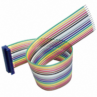
MDM Cable Assembly
Manufacturer
Red Lion Controls
Datasheet
1.HWK70000.pdf
(4 pages)
Specifications of HWK70000
Accessory Type
Cable
Lead Free Status / RoHS Status
Lead free / RoHS Compliant
For Use With/related Products
MDMU Series
Lead Free Status / RoHS Status
Lead free / RoHS Compliant
Other names
RLC70


SPECIFICATIONS (Cont’d)
13. COMMON MODE REJECTION RATIO: 70 dB.
14. INPUT IMPEDANCE: 1000 M
15. TEMPERATURE EFFECTS:
16. CONSTRUCTION: High impact black plastic case. (Mounting clip
17. RELATIVE HUMIDITY: Less than 85% RH.
18. WEIGHT:
INSTALLATION
board mount design. The panel mount units are provided with a mounting clip
to securely hold the unit in the panel cutout.
Panel mount installation:
1. Cut panel opening to
2. Install MDMV unit through
3. Slide mounting clip over rear
Note: Hold the MDMV front
PCB mount installation:
1. Prepare printed circuit board hole pattern to the specifications.
2. Unit should be hand soldered using good soldering techniques and hand
MDMV SIGNAL INPUT
zero adjustment. Signal inputs are not floating. The calibration does not require
adjustment, since the unit has been calibrated at the factory.
condition. The unit will display a minus sign when the input high terminal is
negative with respect to the input low terminal.
BACKPLANE
BACKPLANE
Operating Range: 0 ° to 70 ° C
Storage Temperature: -40 ° to 80 ° C
Temperature Coefficient: 100 ppm/ ° C
included with panel mount models.)
Reflective Panel Mount: 0.76 oz (11 g);
Reflective PCB Mount: 0.54 oz (7.8 g)
Backlit Panel Mount: 0.96 oz (13.6 g);
Backlit PCB Mount: 0.75oz (10.4 g)
The MDMV meters are available in either a panel mount or printed circuit
specified
Remove burrs and clean
panel opening.
panel cutout as shown in
Figure 1.
of unit until clip is against
back of panel. The unit has
slots for the locking tabs to
hold it in the panel opening.
bezel in place when sliding
the mounting clip in to
position.
cleaned if necessary.
The MDMV signal input range is from 0 to ±199.9 mVDC with automatic
If the input signal exceeds 200 mV, the module will go into an overrange
Note: Incorrect supply polarity may permanently damage the unit.
COMMON
COMMON
INLO
+5V
INHI
dimensions.
1MΩ
CIRCUITRY
BLOCK DIAGRAM
PROCESS
BEZEL
FIGURE 2
MOUNTING CLIP
+5V
FIGURE 1
EXISTING PANEL THICKNESS
.031" to .125"
(.79 to 3.18)
BATTERY
A
V
m
µ
DP1
DP2
DP3
LOCKING
TAB
2
WIRING CONNECTIONS
terminal pins located on the back of the
unit. The terminal pins are on 0.100"
center lines and can be mated with the
RLC Model HWK7 cable assembly or
many
connectors. When wiring the unit, refer to
Figure 3 to identify the wire position with
the proper function.
should be observed when running the
signal wires. A length of wire can act like
an antenna, and the closer it is to a source
of electrical noise, the more it becomes
susceptible to that noise.
1. Never run signal wires in the same conduit or raceway with A.C. power lines,
2. Signal wires within enclosures should be routed as far away as possible from
3. When shielded wire is used, connect the shield to the common of the MDMV
4. Connect common of the MDMV to machine ground at one point only.
PIN FUNCTIONS
* Note: All annunciators must be tied to either BACK PLANE or BACKPLANE
HANDLING PRECAUTIONS: This assembly contains electronic circuits
The electrical connections are made via
There are certain considerations that
These are a few rules that should be followed when running these wires.
conductors feeding motors, solenoids, SCR controls, heaters, etc.
contactors, control relays, transformers, and other noisy components.
unit, and leave the other end of the shield disconnected and insulated from
machine ground.
that are damaged by static electricity. Before handling the assembly,
discharge stray static electricity on your body by touching an earth ground
point. It is also important to handle the unit by the bezel assembly only.
Additionally, if it is necessary to handle a circuit board, be certain that hands
are free from dirt, oil, etc., to avoid circuit contamination that may lead to
malfunction.
BACK PLANE
BACK PLANE
standard
COMMON
COMMON
INPUT LO
INPUT HI
+5 V
DP3
DP2
DP1
BAT
m
V
A
μ
0.100"
-
-
-
-
-
-
-
-
-
-
-
-
-
-
-
+5 VDC Positive Supply Terminal.
Negative Supply Terminal.
Negative Supply Terminal.
Signal Input Low Terminal.
Normally connected to Common.
Signal Input High Terminal.
Back Plane Not Terminal. Any annunciator and/or
decimal point will appear when its terminal is
connected to this terminal.
Back Plane Terminal. Any annunciator and/or decimal
point NOT in use must be connected to this terminal.
Thousandths decimal point position. *
Hundredths decimal point position. *
Tenths decimal point position. *
Low battery annunciator. *
Milli annunciator. *
Micro annunciator. *
Volt annunciator. *
Ampere annunciator. *
center
line
FIGURE 3
Related parts for HWK70000
Image
Part Number
Description
Manufacturer
Datasheet
Request
R

Part Number:
Description:
Bezel Kit, SCUBD
Manufacturer:
Red Lion Controls
Datasheet:

Part Number:
Description:
Counter
Manufacturer:
Red Lion Controls
Datasheet:
Part Number:
Description:
Miniature Length Sensor
Manufacturer:
Red Lion Controls
Datasheet:
Part Number:
Description:
Model Lsc - Single Channel Output Length Sensor
Manufacturer:
Red Lion Controls
Datasheet: