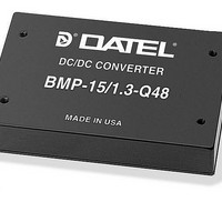
BMP-5/5-3.3/4-D24-C Murata Power Solutions Inc, BMP-5/5-3.3/4-D24-C Datasheet - Page 4

BMP-5/5-3.3/4-D24-C
Manufacturer Part Number
BMP-5/5-3.3/4-D24-C
Description
DC/DC TH 35W 24-5/3.3V XMP
Manufacturer
Murata Power Solutions Inc
Series
BMPr
Datasheet
1.BMP-55-3.34-D24-C.pdf
(5 pages)
Specifications of BMP-5/5-3.3/4-D24-C
Product
Isolated
Output Power
25 W
Input Voltage Range
18 V to 36 V
Input Voltage (nominal)
24 V
Number Of Outputs
2
Output Voltage (channel 1)
5 V
Output Current (channel 1)
5 A
Output Voltage (channel 2)
3.3 V
Output Current (channel 2)
4 A
Isolation Voltage
1.5 KV
Lead Free Status / Rohs Status
Lead free / RoHS Compliant
Performance/Functional Specifications
On/Off Control (Standard)
The On/Off Control pin (pin 5) may be used for remote on/off operation. As
shown in Figure 6, the control pin has an internal 10kΩ pull-up resistor to
approximately 10V. The converter is designed so that it is enabled when the
control pin is left open (normal mode) and disabled when the control pin is
pulled low (to less than +1.2V relative to –Input, pin 2).
Dynamic control of the on/off function is best accomplished with a mechani-
cal relay or an open-collector/open-drain drive circuit (optically isolated if
appropriate). The drive circuit should obviously be able to sink approximately
1.5mA when activated and withstand more than 10 Volts when deactivated.
Applying an external voltage to pin 5 when no input power is applied to the
converter can cause permanent damage to the converter. The on/off control
function, however, is designed such that the converter can be disabled (pin
5 pulled low) while input power is ramping up and then "released" once the
input has stabilized. Under these circumstances, it takes approximately 30ms
for the output of the fully loaded DC/DC to ramp up and settle to within ±1%
of its fi nal value after the converter has been turned on.
Output Trimming
The total output voltage span of the 5 Volt output, from +5V Output (pin 9)
to Output Return (pin 8) may be trimmed ±5% via a single trimpot or fi xed
resistor. The trimpot should be connected as shown in Figure 3 with its wiper
connected to pin 10 (Trim). A trimpot can also be used to determine the value
of a single fi xed resistor which can be connected between pin 10 (Trim) and
pin 9 (+5V Output) to trim "down" the output voltages, or between pins 10
(Trim) and 8 (Output Return) to trim "up" the output voltages. Fixed resistors
should have absolute TCR's less than 100ppm/°C to ensure stability.
Case Connection
Unlike most other DC/DC converters, BMP DC/DC's do not have their metal
case connected to one of their input pins. The "uncommitted" case is con-
nected to pin 4 which, depending on your system confi guration, should be
connected to either +Input (pin 3) or –Input (pin 2).
www.murata-ps.com
5V and 3.3V, 2" x 3" Watt, Dual Output DC/DC Converters
Note: Resistor values are in kΩ. Accuracy of adjustment is subject to toler-
ances of resistors and factory-adjusted output accuracy.
VO = desired output voltage.
3
2
3
2
3
2
Figure 4. +5VOUT Trim Down Connections Using A Fixed Resistor
Figure 5. +5VOUT Trim Up Connections Using A Fixed Resistor
+INPUT
+INPUT
+INPUT
–INPUT
–INPUT
–INPUT
Figure 3. +5VOUT Trim Connections Using A Trim Pot
Technical enquiries email: sales@murata-ps.com, tel:
Figure 2. Driving the On/Off Control Pin
R
T
DOWN
R
+3.3V OUTPUT
+3.3V OUTPUT
+3.3V OUTPUT
T
UP
+5V OUTPUT
+5V OUTPUT
+5V OUTPUT
(k ) =
(k ) =
3
5
2
OUTPUT
RETURN
OUTPUT
RETURN
OUTPUT
RETURN
+INPUT
ON/OFF
CONTROL
–INPUT
TRIM
TRIM
TRIM
2.49(V
5 – V
V
6.30
O
– 5
O
10
10
10
7
9
7
9
7
9
8
8
8
O
– 2.53)
R
TRIM DOWN
BMP Models
R
+10V
TRIM UP
–16.2
MDC_BMP-5.5.B01 Page 4 of 5
10k
–16.2
20k
5-22
Turns
+3.3V LOAD
+3.3V LOAD
+3.3V LOAD
+5V LOAD
+5V LOAD
+5V LOAD
+1 508 339 3000


