XCS-A502 TELEMECANIQUE, XCS-A502 Datasheet
XCS-A502
Specifications of XCS-A502


Related parts for XCS-A502


XCS-A502 Summary of contents
Page 1
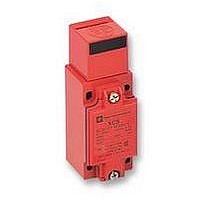
... Components for safety applications Guard switches Metal, turret head, types XCS-A, XCS-C and XCS-E Double insulated, turret head, types XCS-PA, XCS-TA and XCS-TE Presentation Switches with or without locking of the actuator Pages 2/18, 2/19, 2/16, 2/17, 2/21 Switches with or without locking of the actuator ...
Page 2
... IEC 204- 204-1, EN 1088, EN 292 Product certifications UL, CSA, BG Protective treatment Standard version : “TC” Ambient air temperature Operation : - 25… 25… for XCS-E and - 25… for XCS-TE) Storage : - 40… Vibration resistance 5 gn (10…500 Hz) conforming to IEC 68-2-6 Shock resistance 10 gn (duration 11 ms) conforming to IEC 68-2-27 ...
Page 3
... XCS-A, XCS-C and XCS-E (1) Cable entries tapped M20 x 1.5 References, characteristics Without locking of actuator Without 1 orange LED 1 orange LED 24/ 110/240 V ( N/C contact with positive opening operation) XCS-A502 XCS-A512 XCS-A522 XCS-A702 XCS-A712 XCS-A722 XCS-A802 – – 0.440 0.440 0.440 not shown under general characteristics (page 2/15) Maximum : 0.5 m/s, minimum : 0.01 m/s XCS-C : > ...
Page 4
... N/C safety contacts. (3) For use on a 110/120 220/240 V, remove the LED indicator module. (4) Schematic diagrams shown represent the contact states whilst the actuator is inserted in the head of the switch. (5) Units supplied with a single green LED. , types XCS-A, XCS-C and XCS-E ( (50/ ...
Page 5
... XCS-C : > 1500 N ; XCS-E : 2000 N > 1 million operating cycles For maximum durability : 600 operating cycles per hour 20 N XCS-A, XCS cable entry. XCS cable entries. Entries tapped for n 13 cable gland conforming 68-300 (DIN Pg 13.5). Clamping capacity mm. Straight actuator Wide actuator XCS-Z01 XCS-Z02 0 ...
Page 6
... N/C safety contacts. (3) For use on a 110/120 220/240 V, remove the LED indicator module. (4) Schematic diagrams shown represent the contact states whilst the actuator is inserted in the head of the switch. (5) Units supplied with a single green LED. , types XCS-A, XCS-C and XCS-E ( (50/ ...
Page 7
... Maximum : 0.5 m/s, minimum : 0.01 m/s XCS-C : > 1500 N ; XCS-E : 2000 N > 1 million operating cycles For maximum durability : 600 operating cycles per hour 20 N XCS-A, XCS cable entry. XCS cable entries. Entries tapped for 1/2" NPT (USAS B2-1) conduit. Straight actuator Wide actuator XCS-Z01 XCS-Z02 0 ...
Page 8
... N/C safety contacts. (3) For use on a 110/120 220/240 V, remove the LED indicator module. (4) Schematic diagrams shown represent the contact states whilst the actuator is inserted in the head of the switch. (5) Units supplied with a single green LED. , types XCS-A, XCS-C and XCS-E ( (50/ ...
Page 9
... XCS-C, head slot XCS-E Set of 10 pairs of XCS-C, – keys for interlock XCS-E “forced opening” device (1) Lock supplied as standard with XCS-E switches : key withdrawal in LOCK and UNLOCK positions. Reference Weight kg XCS-Z31 0.040 XCS-Z32 0.040 XCS-Z41 0.175 XCS-Z45 ...
Page 10
... Components for safety applications Guard switches Metal, turret head, types XCS-A, XCS-C and XCS-E References : Dimensions pages 2/18 to 2/21 Schemes : pages 2/25 to 2/27 XCS-Aiii ( (1) 1 tapped entry for cable gland Ø elongated holes Ø 7.3 x 5.3 XCS-Eiiii (1) 1 tapped entry for cable gland Ø ...
Page 11
... Adaptor (supplied with actuator XCS-Z01) for replacing, without drilling additional fixing hole, an XCK-J safety limit switch with actuator ZCK-Y07 by an XCS- safety limit switch with actuator XCS-Z01 Ø elongated holes Ø 5 XCS-Z03 30 11 Ø5,3 2,5 Operating radius required for actuator ...
Page 12
... Components for safety applications Guard switches Metal, turret head, types XCS-A, XCS-C and XCS-E References : Setting-up, schemes pages 2/18 to 2/21 Dimensions : pages 2/23 and 2/24 Setting-up Function diagrams XCS-i5iii XCS-i7iii 21-22 22,5 21 13-14 33-34 Schemes Note : These schemes are given as examples only, the designer must refer to the relevant safety standards for guidance. ...
Page 13
... References : pages 2/18 to 2/21 Dimensions : pages 2/23 and 2/24 Wiring to category 1 (EN 954-1) Wiring examples with protection fuse to prevent shunting of the N/C contact, either by cable damage or by unauthorised tampering. Locking on de-energisation N/C + N/O + N/O XCS-E53i ( ( (1) Solenoid (2) Auxiliary contact E1-E2 : Solenoid supply ...
Page 14
... The risk assessment (EN 1050) will help the designer to determine the most appropriate risk reduction methods and the part played by the safety related parts of the control system in reducing the risk. For further information, please consult your local Customer support centre. Locking on energisation N/C + N/C + N/O XCS-E75i (2) (1) KM ...