IFMR0036 Red Lion Controls, IFMR0036 Datasheet - Page 5
IFMR0036
Manufacturer Part Number
IFMR0036
Description
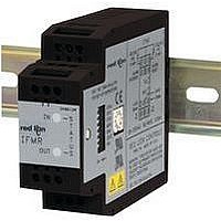
Isolation Amplifier
Manufacturer
Red Lion Controls
Type
Speedr
Specifications of IFMR0036
Width
3.12"
Signal Input Type
Selectable Current Or Voltage
Configuration Setup
DIP Switch
Supply Voltage Max
32VDC
Iso-amp Mounting Type
DIN Rail
Display Alarm Type
Relay
Input Accuracy
± 0.1% Of FS
Application
The IFMR utilizes a seven position DIP switch, a rotary switch, a pushbutton and two indication LEDs to accomplish input circuit configuration, operational parameter set-up, input signal, and relay status indication
Brand/series
IFMR Series
Contact Form
SPDT
Current Rating
5 A
Dimensions
27.5mmW×4.2mmH×79.2mmD
Display Type
LED
Input Type
Analog
Mounting Type
DIN Rail
Output Type
Relay
Power, Rating
2 W
Primary Type
Controller
Sensor, Input
12 VDC
Standards
cURus, CE
Temperature, Operating
0 to +50 °C
Termination
Screw
Voltage, Rating
9 to 32 VDC
Voltage, Supply
9-32 VDC
Signal Output Type
Current
Rohs Compliant
Yes
Lead Free Status / RoHS Status
Lead free / RoHS Compliant
For Use With
Sensors/Switches/TTL


RELAY INDICATION
Overspeed: The Relay LED (red) turns on to indicate the input signal
Underspeed: The Relay LED (red) turns on to indicate the input
Invalid Entry during Set-up: The Input LED (green) and the Relay
1.0 Operating Mode
2.0 On-Line Trip Frequency Setting Using Actual Input Signal or Frequency Generator
BLINKS
OUTPUT
BLINKS
OUTPUT
has exceeded the trip frequency.
signal is below the trip frequency setting.
LED (red) alternately blink until a valid entry is made.
GREEN
INPUT
GREEN
INPUT
LED
RED
LED
OFF
LED
RED
LED
OFF
O U
O U
IN
IN
T
T
PREFERRED
Step 2.2
Step 1.4
Step 2.4
Step 1.3
Step 1.2
METHOD
PUSH-BUTTON
PUSH-BUTTON
ROTARY
SWITCH
Setting ‘2’
Selected
4
4
Step 1.1
Step 2.1
0
5
5
5
6
6
7
7
Factory Setting Example
1.1 Place DIP switch 4 to the ON (up) position and DIP switches 5, 6, and 7 as shown.
1.2 Green input LED blinks the setting corresponding to the Operating Mode shown below, pauses
*
1.3 Press the push-button. The Green input LED blinks rapidly to indicate the Operating mode
1.4 Turn the rotary switch to the selected numerical value for output desired (see the list in Step 1.2).
1.5 Press the push-button. The Green input LED blinks the value entered, pauses, and repeats the
*
2.1 Place DIP switch 4 to the ON position and DIP switches 5, 6, and 7 as shown.
2.2 Green input LED blinks the existing Trip Frequency setting as shown in the examples below. Six
2.3 Apply the desired Trip Frequency to the signal input pin.
2.4 Press the push-button. The Green input LED blinks rapidly. The acquisition process takes two
2.5 Press the push-button. The Green input LED blinks the new Trip Frequency setting. This section
*
Setting Operating Mode
Refers to initial application of power to the IFMR, not the input frequency.
If Red output LED blinks, the rotary switch numerical value is invalid. Repeat Steps 1.4 and 1.5.
Section complete; place DIP switch 4 to the down position for normal operation, or change DIP
If Red relay LED blinks, the new Trip Frequency is invalid, outside the acceptable 0.1 Hz to 25
Section complete; place DIP switch 4 to the down position for normal operation, or change DIP
Otherwise, continue with Step 1.3.
If the new Operating mode setting is acceptable, this section is complete
If the new Operating mode setting is not the desired setting, repeat Steps 1.3, 1.4, and 1.5.
switches 5, 6, and 7 for the next Configuration Section.
If the new Trip Frequency setting is valid, the Green input LED turns on solid. Continue to
Step 2.5.
KHz range. Repeat Steps 2.3 and 2.4.
To verify Trip Frequency setting, see Step 2.2.
switches 5, 6, and 7 for the next Configuration Section.
If existing operating mode setting is your desired requirement, this section is complete
If existing Trip Frequency setting is your desired requirement, this section is complete
1
1
2
3
4
5
6
and repeats the value.
setting is now accessed.
new operation setting.
full digits of numerical information blink with a 2 sec. pause between digits and a 4 sec. pause
at the end, before repeating. The first five digits are the existing Trip Frequency magnitude. The
sixth digit is the frequency resolution (the number of digits to the right of the decimal point).
Otherwise, continue with Step 2.3.
seconds plus one period of the input signal.
is complete
1 blink
2 sec pause
single flash
2 sec pause
single flash
2 sec pause
single flash
2 sec pause
single flash
2 sec pause
single flash
4 sec pause
Frequency
Result: 10,000 Hz
0
OVERSPEED trip, automatic Release upon return to normal
OVERSPEED latched trip, Release only after ALM Reset pulled to Common
UNDERSPEED trip, automatic Release upon return to normal
UNDERSPEED trip, start-up condition
UNDERSPEED latched trip, Release only after ALM Reset pulled to Common
UNDERSPEED latched trip, start-up condition
pulled to Common
Operating Mode
Trip Frequency
Minimum Response
Trip Point Offset
Trip Point Hysteresis
0
0
*
5
.
0
Resolution
1
0
0
0
0
0
0
setting
Resolution
Frequency
Setting
10000
1
0
0
1
FACTORY SETTINGS
*
ignored, automatic Release upon return to normal
Parameter
Low Speed Operation, Trip on Overspeed
10 KHz
5 msec
None
0.25%
*
2
ignored, Release only after ALM Reset
2 blinks
2 sec pause
5 blinks
2 sec pause
single flash
2 sec pause
5 blinks
2 sec pause
single flash
2 sec pause
2 blinks
4 sec pause
Frequency
5
Result: 250.50 Hz
Additional Example
0
5
0
*
Resolution
.
2
5
0
5
0
2
2
setting
Resolution
Frequency
*
*
.
.
Related parts for IFMR0036
Image
Part Number
Description
Manufacturer
Datasheet
Request
R

Part Number:
Description:
Counter
Manufacturer:
Red Lion Controls
Datasheet:
Part Number:
Description:
Miniature Length Sensor
Manufacturer:
Red Lion Controls
Datasheet:
Part Number:
Description:
Model Lsc - Single Channel Output Length Sensor
Manufacturer:
Red Lion Controls
Datasheet: