SNAP-AIMA-32 OPTO 22, SNAP-AIMA-32 Datasheet - Page 2
SNAP-AIMA-32
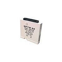
Manufacturer Part Number
SNAP-AIMA-32
Description
I/O Module
Manufacturer
OPTO 22
Type
Inputr
Specifications of SNAP-AIMA-32
Accessory Type
I/O Module
Leaded Process Compatible
No
Peak Reflow Compatible (260 C)
No
Brand/series
SNAP Series
Connection To Host
Backplane
Current, Input
150 mA
Dimensions
82.55mmL×18.29mmW×90.17mmH
Input
-20 to +20 mA
Input Type
Analog
Input, Range
-20 to +20 mA
Mounting Type
PCB
Number Of Channels
32
Primary Type
Control
Special Features
Transformer Isolation, Optical Isolation
Voltage, Isolation
1500 V
Voltage, Supply
5 VDC
For Use With
SNAP PAC Brains
Lead Free Status / RoHS Status
Contains lead / RoHS non-compliant


SNAP Analog Input Modules
Current Input Module, -20 mA to +20 mA, 32 Channels
Specifications
Description
The SNAP-AIMA-32 and
SNAP-AIMA-32-FM modules
provide 32 channels of input
with an input range of -20mA
to +20mA. Check the table on
page 2
compatibility.
These modules DO NOT supply
loop excitation current.
The SNAP-AIMA-32-FM is Factory Mutual approved.
Since all inputs share a common reference, the module must be
installed at the beginning or end of a typical 4–20 mA loop. If you
are using both standard and self-sourcing transmitters, either put
the transmitters on different modules or use different power
supplies. (If you need channels that are isolated from each other on
the same module, see Opto 22 form #1182.)
See the dimensional drawing for the modules on
Input Range
Resolution
Input Filtering
Data Freshness (Max)
DC Common Mode Rejection
AC Common Mode Rejection
Maximum Survivable Input
Maximum Operating Common
Mode Voltage
Accuracy
DRIFT: Gain Temperature
Coefficient
DRIFT: Offset Temperature
Coefficient
Isolation
Power Requirements
Input Resistance - Single
Ended
Operating Temperature
Storage Temperature
for I/O processor
-20 mA to +20 mA
0.8 microamps
-3 dB @ 31 Hz
1.15 s
>-120 dB
>-120 dB @ 60 Hz
36 mA or 9 VDC
250 V
0.05% (10 microamps)
30 PPM/ °C
15 PPM/ °C
1500 V
5 VDC (±0.15 ) @ 150 mA
200 ohms (each channel)
0 °C to 70 °C
-25 °C to 85 °C
page
31.
Wiring
SNAP TEX cables and a breakout rack are available separately for
wiring points to field devices (see form #1756, the SNAP TEX Cables
& Breakout Boards Data Sheet). The SNAP-HD-BF6 cable connects
the module to the breakout rack, which can then be wired to field
devices. (NOTE: The SNAP-HD-CBF6 wiring harness with flying
leads is not recommended for this module.)
CAUTION: We strongly recommend that you use the breakout rack
with these modules. Miswiring of any point on the module can
cause severe out-of-warranty damage. The breakout rack protects
the module from many wiring errors.
if you are using the module with loop power (2-wire) devices,
connect to the SNAP-AIMA-HDB or SNAP-AIMA-HDB-FM rack. If
you are using the module with self-powered devices (4-wire), do
not use the SNAP-AIMA-HDB (or -FM) boards, which have a current
limiter. Instead, wire to the SNAP-AIV-HDB or SNAP-AIV-HDB-FM.
Correcting for Inverted Scaling
Positive readings for these modules appear as negative values.
Therefore, in order to obtain meaningful readings, use the scaling
feature in PAC Control as follows:
1. In the Add or Edit Analog Point dialog box for each point,
2. Under Scaling, scale each point negatively as shown below:
SNAP-AIMA-32
SNAP-AIMA-32-FM
SNAP-HD-BF6
SNAP-AIMA-HDB
SNAP-AIMA-HDB-FM
choose the scalable version of the module.
Part Number
32-channel analog current input,
-20 mA to +20 mA
Wiring harness for SNAP-AIMA-32
modules and breakout racks
Breakout racks for SNAP-AIMA-32
and SNAP-AIMA-32-FM
Description
PAGE
11
Related parts for SNAP-AIMA-32
Image
Part Number
Description
Manufacturer
Datasheet
Request
R

Part Number:
Description:
I/O Module, Snap Analog, Single Channel, 0 Volt DC To 10 Volt DC Output
Manufacturer:
OPTO 22
Datasheet:

Part Number:
Description:
SNAP Rack DIN-rail Adapter Clip
Manufacturer:
OPTO 22
Datasheet:

Part Number:
Description:
SNAP 8-Ch -10VDC To +10VDC Analog Input Module
Manufacturer:
OPTO 22
Datasheet:

Part Number:
Description:
Brains; SNAP; 32-Channel; Digital Board; Pamux Protocol
Manufacturer:
OPTO 22
Datasheet:

Part Number:
Description:
Controller, SNAP; 2 COM Ports; Panel Mount; 5 VDC + 5% @ 500 mA (Max.)
Manufacturer:
OPTO 22
Datasheet:

Part Number:
Description:
I/O Module
Manufacturer:
OPTO 22
Datasheet:

Part Number:
Description:
Learning Center
Manufacturer:
OPTO 22
Datasheet:
Part Number:
Description:
Snap Analog Input Module, SNAP 2 Channel Thermo I/P, Types B,C,D,G,N,T,R,S
Manufacturer:
OPTO 22
Part Number:
Description:
SNAP 4-Ch 90-140 VAC Digital Input Module, Factory Mutual Approved
Manufacturer:
OPTO 22

Part Number:
Description:
Solid State Relays, Accessories
Manufacturer:
OPTO 22
Datasheet:
