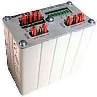
SNAP-B3000-MODBUS OPTO 22, SNAP-B3000-MODBUS Datasheet - Page 9

SNAP-B3000-MODBUS
Manufacturer Part Number
SNAP-B3000-MODBUS
Description
G4 DIGITAL I/O MODULE
Manufacturer
OPTO 22
Type
PC Basedr
Specifications of SNAP-B3000-MODBUS
Leaded Process Compatible
No
Peak Reflow Compatible (260 C)
No
Brand/series
SNAP Series
Communication
RS-422/485
Current, Input
1 A
Dimensions
3.3"L×1.82"W×3.62"H
Input Type
Analog/Digital
Mounting Type
Rack
Number Of Expansion Modules
8, 12/16
Number Of Inputs
32
Number Of Outputs
32
Output Type
Analog/Digital
Primary Type
Controller
Terminal Type
2/4 Wire
Termination
2/4 Wire
Voltage, Supply
5-5.2 VDC
Lead Free Status / RoHS Status
Contains lead / RoHS non-compliant
For Use With
I/O Rack
Modbus Analog and Digital SNAP Brain
SNAP-B3000-Modbus I/O Mapping (Continued)
The table below shows the possible uses for all points on the relay
rack. Coils and Inputs are bit masks and contain 0 or 1 only. Since
digital counters and module configuration require more than one
bit, they are handled in Input and Holding Registers, which are 16-
bit registers.
Note that you address the same point using different sets of 32
numbers for different purposes.
For example, suppose you have a digital module in position 0 with
four points of I/O.
•
Mapping Information
129–160 Counter state
97–128
33–64
65–96
33–64
65–96
33–64
33–48
© 2007 Opto 22. All rights reserved. Dimensions and specifications are subject to change. Brand or product names used herein are trademarks or registered trademarks of their respective companies or organizations.
1–32
1–32
1–32
1–32
Coil 4 gives the status of the output at point 4.
65
SALES 800-321-6786 • 951-695-3000 • FAX 951-695-3095 • sales@opto22.com • SUPPORT 800-835-6786 • 951-695-3080 • FAX 951-695-3017 • support@opto22.com
Digital outputs
Clear on-latch
Clear off-latch
Counter clear
Digital inputs
State of on-latches
State of off-latches
Analog inputs
Digital counters
Analog outputs
Module configuration
Store/clear configuration
Use Holding Register 65 to copy the current configuration to flash memory. When a power cycle occurs on the relay rack, modules will be
reconfigured with the values from the flash memory. Store the configuration in flash only when it changes. Make sure you don’t put store/
clear in a loop, or you’ll wear out flash memory.
NOTE: For brain firmware earlier than R 1.19 (dated 6-8-01), you must use the Preset Single Register Modbus command (06), not the
Preset Multiple Registers Modbus command (10 hex), to copy to flash. For later firmware, use either command.
Holding Registers (4x)
Input Registers (3x)
Inputs (1x)
Coils (0x)
1 bits = on; 0 bits = off
1 bits clear on-latches
1 bits clear off-latches
1 bits clear counters
1 bits activate counters
1 bits = on; 0 bits = off
1 bits = on; 0 bits = off
1 bits = on; 0 bits = off
Input values only (Outputs will return 0.)
If counters are enabled, digital counter val-
ues are returned here.
(Reading inputs here will return 0.)
16 module positions (See
Modbus I/O Configuration” on page
1 stores configuration values in flash mem-
ory; 0 clears flash.
“SNAP-B3000-
Opto 22 • 43044 Business Park Drive • Temecula, CA 92590-3614 • www.opto22.com
•
•
Or suppose you have a digital input module in position 1 with four
points of I/O.
•
•
•
•
Coil 36 clears an on-latch for the output at point 4.
Coil 68 clears an off-latch for the output at point 4.
Input 6 gives the status of the input at point 6.
Coil 134 activates the counter for the input at point 6.
Input Register 38 returns the value of the counter for the input
at point 6.
Coil 102 clears the counter for the input at point 6.
10.)
You must enable or disable digital counters here.
Digital counter values are returned under Input
Registers.
If you are using dual-channel analog outputs, you can
read or write all registers to get all the data. But if you
are using single-channel analog outputs, you must skip
the odd-numbered registers and read or write to even-
numbered registers only.
Latch bits are cleared automatically when the I/O unit
clears the physical latch.
PAGE
9


