SNAP-AITM OPTO 22, SNAP-AITM Datasheet - Page 2
SNAP-AITM
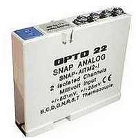
Manufacturer Part Number
SNAP-AITM
Description
I/O Module
Manufacturer
OPTO 22
Type
Inputr
Specifications of SNAP-AITM
Accessory Type
Thermocouple Module
Leaded Process Compatible
No
Peak Reflow Compatible (260 C)
No
Signal Input Type
-150 To 150mV / -75 To 75mV
No. Of Analog Inputs
2
Brand/series
SNAP Series
Connection To Host
Backplane
Current, Input
170 mA
Dimensions
82.55mmL×18.29mmW×90.17mmH
Input
-150 to +150/-75 to +75 mVDC
Input Type
Analog
Input, Range
-150 to +150/-75 to +75 mVDC
Mounting Type
PCB
Number Of Channels
2
Number Of Inputs
2 Channels
Primary Type
Control
Resistance, Input
100 Megohms
Special Features
Transformer Isolation, Optical Isolation, Thermocouple Input
Standards
UL, CSA, CE Certified
Temperature, Operating
0 to +70 °C
Time, Response
66 ms
Voltage, Isolation
1500 V
Voltage, Supply
5 VDC
For Use With
SNAP PAC System
Lead Free Status / RoHS Status
Contains lead / RoHS non-compliant


PAGE
2
Transformer and Optical Isolation
All SNAP analog input modules are transformer isolated and
optically isolated from all other modules and from the SNAP I/O
processor. The modules in this data sheet do not have channel-to-
channel isolation, however. (If you need isolated analog modules,
see Opto 22 form #1182.)
Optical isolation provides 4,000 volts of transient (4,000 V for
1 ms) protection for sensitive control electronics from industrial
field signals.
Transformer isolation prevents ground loop currents from
flowing between field devices and causing noise that produces
erroneous readings. Ground loop currents are caused when two
grounded field devices share a connection, and the ground
potential at each device is different.
IMPORTANT: Since these analog input modules provide multiple
single-ended input channels with a common reference, the
channels are not isolated from each other. (See Opto 22 form #1182
for isolated modules.)
Installation
Note module and processor compatibility in the following table:
All modules can be used with SNAP PAC rac ks and can be placed in
any position on the rack. Two- and four-channel modules can also
be used with legacy SNAP M-series and B-series mounting racks.
(For more information on using legacy hardware, see form #1688,
the SNAP PAC System Migration Technical Note.)
Modules snap securely into place in the row of connectors on the
mounting rack. Each module connector has a number. Analog input
modules and other types of SNAP I/O modules are mounted on the
module connectors starting at module position zero.
Modules require a special tool (provided) for removal.
32-channel inputs
8-channel inputs
4-channel inputs
2-channel inputs
Modules
SNAP PAC R-series controllers and
SNAP PAC brains
SNAP PAC R-series controllers and
SNAP PAC brains
Also the following legacy brains:
SNAP Ethernet, SNAP Simple, SNAP
Ultimate; SNAP-DNP-ASDS; SNAP OEM
SNAP PAC R-series controllers and
SNAP PAC brains
Also the following legacy brains:
SNAP Ethernet, SNAP Simple, SNAP
Ultimate; SNAP-DNP-ASDS; SNAP OEM;
serial SNAP brains (B3000, Modbus,
Profibus); B3000-HA; B6
Compatible I/O Processors
The following diagram shows part of a SNAP PAC mounting rack.
1. Place the rack so that the module connector numbers are right-
2. Position the module over the module connector, aligning the
3. With the module correctly aligned, push on the module to snap
4. (Optional) Use standard 4-40 x 1/4 truss-head Phillips hold-
5. Follow the wiring diagrams beginning on
For faster, easier field wiring installation and maintenance, use
SNAP TEX cables and breakout boards. See Opto 22 form #1756,
the SNAP TEX Cables & Breakout Boards Data Sheet, for compatibility
and specifications.
SNAP Analog Input Modules
Processor connector
side up, with zero on the left, as shown in the diagram above.
(If your rack has screw connectors, the screw connectors will be
at the bottom.)
small slot at the base of the module with the retention bar on
the rack. When positioning modules next to each other, be sure
to align the male and female module keys at the tops of the
modules before snapping a module into position.
it into place.
down screws to secure both sides of each module.
CAUTION: Do not over-tighten screws.
modules to the devices they monitor. Most modules accept up
to 14 AWG wire; the SNAP-AITM-8 accepts a maximum of two
solid 18 AWG wires.
Module
position zero
Module connectors
page 3
Retention bar
to attach
Related parts for SNAP-AITM
Image
Part Number
Description
Manufacturer
Datasheet
Request
R

Part Number:
Description:
POWER SUPPLY, SWITCH MODE, 24V
Manufacturer:
OPTO 22
Datasheet:
Part Number:
Description:
Ethernet, I/O Brain, Rack Mount, 5.0 VDC 0.1 VDC @ 1.0 A; RS-232
Manufacturer:
OPTO 22
Datasheet:

Part Number:
Description:
Programmable Controller
Manufacturer:
OPTO 22
Datasheet:

Part Number:
Description:
Controllers
Manufacturer:
OPTO 22
Datasheet:

Part Number:
Description:
Brains; SNAP; 32-Channel; Digital Board; Pamux Protocol
Manufacturer:
OPTO 22
Datasheet:
Part Number:
Description:
Programmable Logic Controller
Manufacturer:
OPTO 22
Datasheet:

Part Number:
Description:
Power Monitoring Module
Manufacturer:
OPTO 22
Datasheet:

Part Number:
Description:
I/O Module
Manufacturer:
OPTO 22
Datasheet:

Part Number:
Description:
G4 DIGITAL I/O MODULE
Manufacturer:
OPTO 22
Datasheet:

Part Number:
Description:
Programmable Controller
Manufacturer:
OPTO 22
Datasheet:

Part Number:
Description:
Solid State Relays, Accessories
Manufacturer:
OPTO 22
Datasheet:
