M/58112/09 NORGREN, M/58112/09 Datasheet - Page 2
M/58112/09
Manufacturer Part Number
M/58112/09
Description
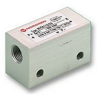
VACUUM GENERATOR
Manufacturer
NORGREN
Datasheet
1.M5811209.pdf
(2 pages)
Specifications of M/58112/09
Operating Pressure Psi Max
8bar
Temperature Max
150°C
Svhc
No SVHC (18-Jun-2010)
Operating Temperature Min
150°C
Pressure Max
8bar
Sound Level Spl
74dB
Operating Pressure Max
8bar
Rohs Compliant
NA
Lead Free Status / RoHS Status
na


Characteristics
Air Consumption
100
90
80
70
60
50
40
30
20
10
Tube Dimensions
Recommended tube dimensions
(internal diameter)
Basic Dimensions
Warning
These products are intended for use in industrial compressed air sys-
tems only. Do not use these products where pressures and tempera-
tures can exceed those listed under ‘Technical Data’.
Before using these products with fluids other than those specified,
for non-industrial applications, life-support systems, or other applica-
tions not within published specifications, consult NORGREN.
Through misuse, age, or malfunction, components used in
fluid power systems can fail in various modes.
N/UK 3.4.005.02
0
(Nl / min.)
0
1 2 3 4 5
M/58112/09
Operating Pressure
6
7
(All values given apply to an atmospheric pressure of 1013 mbar)
8
( bar )
Our policy is one of continued research and development. We therefore reserve the right to amend, without notice, the specifications given in this document.
Vacuum
- 1,0
- 0,9
- 0,8
- 0,7
- 0,6
- 0,5
- 0,4
- 0,3
- 0,2
- 0,1
0
( bar )
0
For your local Norgren Technical Sales Centre phone 0345 662266. For your local Norgren Distributor phone 0345 227777.
1 2 3 4 5
Operating Pressure
IMI Norgren Limited, PO Box 22, Eastern Avenue, Lichfield, Staffordshire WS13 6SB
6
Model
M/58112/09
P-
P+
7
8
( bar )
Compressed air Vacuum
≥
27
42
Note: Values given in the tables are theoretical and apply to an operating pressure of 5 bar
Induced air (Nl/min), free air
Time (sec) for evacuation of 1 litre volume to vacuum
3
Model
M/58112/09 28
Model
M/58112/09
The system designer is warned to consider the failure modes of
all component parts used in fluid power systems and to provide ade-
quate safeguards to prevent personal injury or damage to equipment
in the event of such failure.
System designers must provide a warning to end users in the
system instructional manual if protection against a failure mode
cannot be adequately provided.
System designers and end users are cautioned to review specific
warnings found in instruction sheets packed and shipped with
these products.
G 1/8
≥
R
0
6
- 0,1
0,27
- 0,1
24
- 0,2
0,56
Exhaust
≥
20
6
- 0,2
18
- 0,3
0,89
- 0,3
14
- 0,4
1,44
- 0,4
11
2,00
- 0,5
- 0,5
8
- 0,6
2,88
- 0,6
5,5
- 0,7
4,31
3
- 0,7
- 0,8
7,97
- 0,8
1
0,85
14,36
9/96
Related parts for M/58112/09
Image
Part Number
Description
Manufacturer
Datasheet
Request
R

Part Number:
Description:
Heatsinks Heat Sink for CHB50
Manufacturer:
Cincon
Datasheet:

Part Number:
Description:
Heatsinks 8-36V 5.2mA 22MHz
Manufacturer:
Cincon
Datasheet:
Part Number:
Description:
Heatsinks ABS LCD DISPLAY 4-20mA 800ohm
Manufacturer:
Cincon
Datasheet:

Part Number:
Description:
COIL PWR CHOKE 1.3UH 1.5A SMD
Manufacturer:
Panasonic - ECG
Datasheet:

Part Number:
Description:
PRESSURE SWITCH, ELECTRO/PNEUMATIC
Manufacturer:
NORGREN
Datasheet:
Part Number:
Description:
PRESSURE SWITCH, ELECTRO/PNEUMATIC
Manufacturer:
NORGREN
Datasheet:

Part Number:
Description:
TUBE NUT, 4MM, COMPRESSION
Manufacturer:
NORGREN
Datasheet:
Part Number:
Description:
TUBE NUT, 6MM
Manufacturer:
NORGREN
Datasheet:
Part Number:
Description:
TUBE NUT, 8MM
Manufacturer:
NORGREN
Datasheet:

Part Number:
Description:
ADAPTOR, 4MMX1/8
Manufacturer:
NORGREN
Datasheet:
Part Number:
Description:
ADAPTOR, 8MMX1/8
Manufacturer:
NORGREN
Datasheet:
Part Number:
Description:
ADAPTOR, 8MMX1/4
Manufacturer:
NORGREN
Datasheet:

Part Number:
Description:
E-Series SMT 75 Ohm 17 DB Coupler 5 - 1000 MHZ
Manufacturer:
M/A-COM, Inc.
Datasheet:
Part Number:
Description:
E-series 1 9 Transformer 10 - 75 Mhz
Manufacturer:
M/A-COM
Datasheet: