RTE-P1D12 IDEC, RTE-P1D12 Datasheet

Electromechanical Multifunction Timer

RTE-P1D12

Manufacturer Part Number
RTE-P1D12
Description
Electromechanical Multifunction Timer
Manufacturer
IDEC
Type
Multi-Moder
Datasheet

Specifications of RTE-P1D12

Time Range
0.1 Sec. To 600 Hr.
Peak Reflow Compatible (260 C)
No
Supply Voltage Max
12VDC
Time Range Max
600h
Leaded Process Compatible
No
Mounting Type
8-pin
Switch Function
Delayed DPDT
G
RTE Series
G-8
Operation System
Operation Type
Time Range
Pollution Degree
Over voltage category
Rated Operational
Voltage
Voltage Tolerance
Input off Voltage
Ambient Operating Temperature
Ambient Storage and
Transport Temperature
Relative Humidity
Atmospheric Pressure
Reset Time
Repeat Error
Voltage Error
Temperature Error
Setting Error
Insulation Resistance
Dielectric Strength
Vibration Resistance
Shock Resistance
Degree of Protection
Mounting Position
Dimensions
Weight (Approx.)
*For the value of the error against a preset time, whichever the largest.
TYPE
AF20
24V AC 60Hz/DC
D12
Cert. No. E9950913332316 (EMC, RTE)
cert. No. BL960813332355 (LVD, RTE)
120V AC/60Hz
240V AC/60Hz
RTE-P1, P2
RTE-B1, B2
www.idec.com
AF20
AD24
D12
AF20
AD24
D12
General Specifications
Solid state CMOS Circuit
Multi-Mode
0.1sec to 600 hours
2 (IE60664-1)
III (IE60664-1)
100-240V AC(50/60Hz)
24V AC(50/60Hz)/24V DC
12V DC
85-264V AC(50/60Hz)
20.4-26.4V AC(50/60Hz)/21.6-26.4V DC
10.8-13.2V DC
Rated Voltage x10% minimum
-20 to +65ºC (without freezing)
-30 to +75
35 to 85%RH (without condensation)
80kPa to 110kPa (Operating), 70kPa to 110kPa (Transport)
100msec maximum
±0.2%, ±20msec*
±0.2%, ±20msec*
±0.5%, ±20msec*
±10% maximum
100M minimum (500V DC)
Between power and output terminals: 2000V AC, 1 minute
Between contacts of different poles: 2000V AC, 1 minute
Between contacts of the same pole:1000V AC, 1 minute
10 to 55Hz amplitude 0.5mm2 hours in each of 3 axes
Operating extremes: 98m/sec
Damage limits: 490m/sec
3 times in each of 3 axes
IP40 (enclosure) (IEC60529)
RTE-P1, -B1
6.5VA
11.6VA
3.4VA/1.7W
1.6W
Free
40Hx 36W x 77.9D mm
40Hx 36W x 74.9D mm
RTE-P1
87g
ºC
(without freezing)
RTE Series — Analog Timers
RTE-P2
89g
2
(50G)
2
(10G)
Key features of the RTE series include:
• 20 time ranges and 10 timing functions
• Time delays up to 600 hours
• Space-saving package
• High repeat accuracy of 0.2%
• ON and timing OUT LED indicators
• Standard 8- or 11-pin and 11-blade termination
• 2 form C delayed output contacts
• 10A Contact Rating
USA: (800) 262-IDEC or (408) 747-0550, Canada: (888) 317-IDEC
UL Listed
File No. E66043
RTE-P2, -B2
6.6VA
11.6VA
3.5VA/1.7W
1.6W
RTE-B1, -B2
85g
Contact Configuration
Allowable Voltage /
Allowable Current
Maximum Permissible
Operating Frequency
Rated
Load
Life
Specifications —G-8
Part Number Guide — G-9
Part Number List — G-9
RTE Timing Diagrams — G-10
RTE Accessories — G-12
Instructions: Setting Timer — G-11
RTE Dimensions — G-13
General Timing Diagrams — G-4
Resistive
Inductive
Horse Power Rat-
ing
Electrical
Mechanical
RTE Table of Contents
Contact Ratings
Timers
2 Form C, DPDT
(Delay output)
240V AC, 30V DC / 10A
1800 cycles per hour
10A 240V AC, 30V DC
7A 240V AC, 30V DC
1/6 HP 120V AC, 1/3 HP
240V AC
500,000 op. minimum
(Resistive)
50,000,000 op. minimum

Related parts for RTE-P1D12

RTE-P1D12 Summary of contents

Page 1

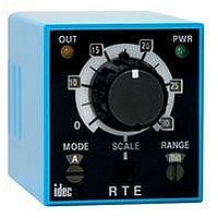
... G-8 RTE Series — Analog Timers Key features of the RTE series include: • 20 time ranges and 10 timing functions • Time delays up to 600 hours • Space-saving package • High repeat accuracy of 0.2% • ...

Page 2

... ON/OFF delay, OFF-delay, one-shot 100 to 240V AC(50/60Hz) Input Voltage 24V AC(50/60Hz)/24V DC 12V DC Part Numbers Power Triggered Voltage 8-Pin Blade 12V DC RTE-P1D12 RTE-B1D12 24V AC/DC RTE-P1AD24 RTE-B1AD24 RTE-P2AD24 100-240V AC RTE-P1AF20 RTE-B1AF20 Time Range Determined by Time Range Selector & Dial Selector Dial ...

Page 3

... When power is turned on while the start input is on, the NO output contact goes on. When a preset time has elapsed after the start input turned off, the NO output contact goes off Terminal No PWR OUT Note : T=Set Time, Ta=Shorter than set time, (1): RTE-P1, (2): RTE-B1, (A): RTE-P2, (B): RTE-B2 www.idec.com G-10 Timing Diagrams RTE-B1 RTE-B2 external start control ...

Page 4

... Use an IEC60127-approved fuse and circuit breaker on the power and output line outside the Electronic Timer. • Do not disassemble, repair, or modify the Electronic Timer. • When disposing of the Electronic Timer industrial waste. RTE Series 7A 5A Mounting B Derating Curve 50º ...

Page 5

... SR3P-05 RTE-P2 SR3P-05C RTE-P1 SR2P-06 RTE-B1 SR3B-05 RTE-B2 — BNDN1000 Panel Mounting Accessories Appearance Use with All RTE timers RTE-P1 (Shown: SR6P-M08G Wiring Socket Adapter) RTE-P2 RTE-P1 RTE-P2 USA: (800) 262-IDEC or (408) 747-0550, Canada: (888) 317-IDEC Timers Applicable Hold-Down Springs Appearance Part No ...

Page 6

... Timers RTE Timer, 8-Pin and 11-Pin with SR6P-S08 or SR6P-S11 Panel Thickness 0.8 to 5mm www.idec.com USA: (800) 262-IDEC or (408) 747-0550, Canada: (888) 317-IDEC Dimensions 13.0 77.9 36.0 13.7 RTE-P1 (8 pin) Terminal Style RTE-P2 (11 pin)Terminal Style RTE-B1/RTE-B2 (11 blade) Terminal Style Panel Mount Adapter 98 maximum Panel Thickness 0 ...

Page 7

... Contact Protection Switching an inductive load generates a counter-electromotive force (back EMF) in the coil. The back EMF will cause arcing, which may shorten the con- tact life and cause imperfect contact. Application of a protection circuit is recommended to safeguard the contacts. ...

Related keywords