PAXTM000 Red Lion Controls, PAXTM000 Datasheet - Page 6
PAXTM000
Manufacturer Part Number
PAXTM000
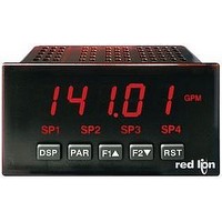
Description
Digital Multifunction Timer
Manufacturer
Red Lion Controls
Type
Timerr
Datasheet
1.PAXTM000.pdf
(28 pages)
Specifications of PAXTM000
Time Range
0.001sec To 1hr
Power Consumption
18VA
Supply Voltage Ac, Min
85V
Signal Input Type
Pulse
Supply Voltage Max
250VAC
Time Range Max
999999h
Character Size
0.56"
Accuracy
±0.01% %
Connection Type
Cage-Clamp
Cut Out, Panel
3.62×1.77 "
Digit Height
0.48
Dimensions
4.2"L×3.8"W×1.95"H
Display Digit Height
0.56 "
Display Resolution
0.001 Sec. (Minimum Digit), 1 hr. (Single Digit)
Display Type
LED
Function
Timer
Humidity
0 to 85% (Max.) RH
Isolation Voltage
2300 V (RMS)
Length, Stripping
0.3 in. Wire
Memory Type
Non-Volatile EEPROM
Number Of Digits
5
Power, Rating
18 VA
Primary Type
Electronic
Range, Measurement
0 to 999999
Special Features
programmable
Standards
cULus Listed, CSA Certified
Temperature, Operating
0 to +50 °C
Termination
Cage Clamp
Torque
4.5 in.-lbs
Voltage, Range
85 to 250 VAC
Voltage, Supply
85 to 250 VAC
Four Separate Displays
Timer, Counter, Real-Time Clock and Date
Display Font Color
Red
No. Of Digits / Alpha
6
Supply Voltage Ac, Max
250V
Rohs Compliant
Yes
Lead Free Status / RoHS Status
Lead free / RoHS Compliant


specific functions. These cards plug into the main circuit board of the meter. The
Plug-in cards have many unique functions when used with the meters.
WIRING OVERVIEW
back of the meter. All conductors should conform to the meter’s voltage and
current ratings. All cabling should conform to appropriate standards of good
installation, local codes and regulations. It is recommended that the power
supplied to the meter (DC or AC) be protected by a fuse or circuit breaker.
meter case against those shown in wiring drawings for proper wire position.
Strip the wire, leaving approximately 0.3" (7.5 mm) bare lead exposed (stranded
wires should be tinned with solder.) Insert the lead under the correct screw-
clamp terminal and tighten until the wire is secure. (Pull wire to verify
tightness.) Each terminal can accept up to one #14 AWG (2.55 mm) wire, two
#18 AWG (1.02 mm), or four #20 AWG (0.61 mm).
EMC INSTALLATION GUIDELINES
Magnetic Interference (EMI), proper installation and wiring methods must be
followed to ensure compatibility in each application. The type of the electrical
noise, source or coupling method into the meter may be different for various
installations. The meter becomes more immune to EMI with fewer I/O
connections. Cable length, routing, and shield termination are very important
and can mean the difference between a successful or troublesome installation.
Listed below are some EMC guidelines for successful installation in an
industrial environment.
1. The meter should be mounted in a metal enclosure, which is properly
2. Use shielded (screened) cables for all Signal and Control inputs. The shield
3.0 I
4.0 W
The Plug-in cards are separately purchased optional cards that perform
Electrical connections are made via screw-clamp terminals located on the
When wiring the meter, compare the numbers embossed on the back of the
Although this meter is designed with a high degree of immunity to Electro-
connected to protective earth.
(screen) pigtail connection should be made as short as possible. The
connection point for the shield depends somewhat upon the application.
Listed below are the recommended methods of connecting the shield, in order
of their effectiveness.
a. Connect the shield only at the panel where the unit is mounted to earth
ground (protective earth).
CAUTION: The Plug-in card and main circuit board contain static
sensitive components. Before handling the cards, discharge static
charges from your body by touching a grounded bare metal
object. Ideally, handle the cards at a static controlled clean
workstation. Also, only handle the cards by the edges. Dirt, oil or
other contaminants that may contact the cards can adversely
affect circuit operation.
NSTALLING
IRING THE
TOP VIEW
P
M
LUG
ETER
-I
N
6
C
To Install:
1. With the case open, locate the Plug-in card connector for the card type to be
2. Install the Plug-in card by aligning the card terminals with the slot bay in the
3. Slide the meter base back into the case. Be sure the rear cover latches fully
4. Apply the Plug-in card label to the bottom side of the meter. Do Not Cover
3. Never run Signal or Control cables in the same conduit or raceway with AC
4. Signal or Control cables within an enclosure should be routed as far as possible
5. In extremely high EMI environments, the use of external EMI suppression
6. Long cable runs are more susceptible to EMI pickup than short cable runs.
7. Switching of inductive loads produces high EMI. Use of snubbers across
Quad Sourcing Open Collector Output Card Supply Select
* If installing the Quad sourcing Plug-in Card (PAXCDS40), set the jumper for
ARDS
installed. The types are keyed by position with different main circuit board
connector locations. When installing the card, hold the meter by the rear
terminals and not by the front display board.*
rear cover. Be sure the connector is fully engaged and the tab on the Plug-in
card rests in the alignment slot on the display board.
into the case.
the vents on the top surface of the meter. The surface of the case must be
clean for the label to adhere properly. Apply the label to the area designated
by the large case label.
b. Connect the shield to earth ground at both ends of the cable, usually when
c. Connect the shield to common of the meter and leave the other end of the
power lines, conductors feeding motors, solenoids, SCR controls, and
heaters, etc. The cables should be ran in metal conduit that is properly
grounded. This is especially useful in applications where cable runs are long
and portable two-way radios are used in close proximity or if the installation
is near a commercial radio transmitter.
from contactors, control relays, transformers, and other noisy components.
devices, such as ferrite suppression cores, is effective. Install them on Signal
and Control cables as close to the unit as possible. Loop the cable through the
core several times or use multiple cores on each cable for additional protection.
Install line filters on the power input cable to the unit to suppress power line
interference. Install them near the power entry point of the enclosure. The
following EMI suppression devices (or equivalent) are recommended:
Therefore, keep cable runs as short as possible.
inductive loads suppresses EMI.
internal or external supply operation before continuing.
the noise source frequency is above 1 MHz.
shield unconnected and insulated from earth ground.
Ferrite Suppression Cores for signal and control cables:
Line Filters for input power cables:
Note: Reference manufacturer’s instructions when installing a line filter.
Snubber: RLC# SNUB0000.
Fair-Rite # 0443167251 (RLC# FCOR0000)
TDK # ZCAT3035-1330A
Steward # 28B2029-0A0
Schaffner # FN610-1/07 (RLC# LFIL0000)
Schaffner # FN670-1.8/07
Corcom # 1 VR3
Related parts for PAXTM000
Image
Part Number
Description
Manufacturer
Datasheet
Request
R

Part Number:
Description:
Counter
Manufacturer:
Red Lion Controls
Datasheet:
Part Number:
Description:
Miniature Length Sensor
Manufacturer:
Red Lion Controls
Datasheet:
Part Number:
Description:
Model Lsc - Single Channel Output Length Sensor
Manufacturer:
Red Lion Controls
Datasheet: