GT3A-2AD24 IDEC, GT3A-2AD24 Datasheet
GT3A-2AD24
Specifications of GT3A-2AD24


Related parts for GT3A-2AD24


GT3A-2AD24 Summary of contents
Page 1
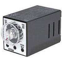
... Storage Temperature Housing Color www.idec.com G-14 GT3A Series — Analog Timers Key features of the GT3A series include: • 4 selectable operation modes on each model • External start, reset, and pause inputs • Panel mount or socket mount • Large variety of timing functions • Power and output status indicating LEDs ...
Page 2
... Delayed 24V DC, 5A Reset to DPDT (resistive load) Gate 180 hours GT3A Series Complete Part No. 8-Pin 11-Pin GT3A-1AF20 GT3A-1EAF20 GT3A-2AF20 GT3A-2EAF20 GT3A-2D12 GT3A-2ED12 GT3A-2AD24 GT3A-2EAD24 GT3A-3AF20 GT3A-3EAF20 GT3A-3D12 GT3A-3ED12 GT3A-3AD24 GT3A-3EAD24 Complete Part No. A (11-pin) B (11-pin) GT3A-4AF20 GT3A-4EAF20 GT3A-4D12 GT3A-4ED12 G GT3A-4AD24 GT3A-4EAD24 ...
Page 3
... Cycle 1 (OFF first) Power (Power) MODE (NC) Delayed Contact C (NO) Indicator Item Terminal No. Cycle 3 (ON first) Power (Power) MODE (NC) Delayed D Contact (NO) Indicator www.idec.com G-16 Timing Diagrams/Schematics GT3A- 1 Timing Diagrams 6 11-Pin (+) 2 10 (-) (+) POWER Operation Set Time 2-7 (8p) 2-10 (11p) 5-8 (8p) 8-11 (11p) 6-8 (8p) ...
Page 4
... Instan- C taneous Contact (NO) Indicator Item Terminal No. Power (Power) Cycle 3 (ON first) (NC) Delayed Contact (NO) MODE (NC) Instan- D taneous Contact (NO) Indicator www.idec.com USA: (800) 262-IDEC or (408) 747-0550, Canada: (888) 317-IDEC GT3A- 2 Timing Diagrams 6 11-Pin (+) 2 10 (-) (+) POWER Operation Set Time 2-7 (8p) 2-10 (11p) 5-8 (8p) ...
Page 5
... Indicator Item Cycle 1 Power (Power) (OFF first) (NC) 1-4, 8 -11(11p) MODE Delayed Contact C (NO) Indicator Item Cycle 3 Power (Power) (ON first) (NC) 1-4, 8 -11(11p) MODE Delayed Contact D (NO) Indicator www.idec.com G-18 GT3A-3 Timing Diagrams 6 11-Pin (+) 2 10 (-) (+) POWER POWER Terminal No. Operation Set Time 2-7 (8p) ...
Page 6
... MODE Gate C Delayed Contact Indicator Set Time Item Power Start Signal OFF-Delay 1 Reset MODE Gate D Delayed Contact Indicator Set Time www.idec.com USA: (800) 262-IDEC or (408) 747-0550, Canada: (888) 317-IDEC GT3A-4 Timing Diagrams Delayed DPDT (Transistor Input Reset Start Gate (-) (+) (-) POWER T Ta Terminal No ...
Page 7
... Power Start Signal ON/OFF-Delay 2 Reset MODE Gate C Delayed Contact Indicator Set Time Item Power Start Signal OFF-Delay 2 Reset MODE Gate D Delayed Contact Indicator Set Time www.idec.com G-20 GT3A- 5 Timing Diagrams Delayed DPDT (Transistor Input Reset Start Gate (-) (+) (-) POWER POWER Terminal No. ...
Page 8
... Signal 2-7 (A) ON/OFF-Delay 3 Reset 6-7 ( MODE Gate 2-5 ( 1-4 D 8-11 (NC) Delayed Contact 1-3 9-11 (NO) POWER Indicator OUT Set Time www.idec.com USA: (800) 262-IDEC or (408) 747-0550, Canada: (888) 317-IDEC GT3A- 6 Timing Diagrams Delayed DPDT (Transistor Input Reset Start Gate (+) (-) POWER POWER ...
Page 9
... Step 3. Set the precise period of time desired by using the www.idec.com G-22 Instructions: Setting GT3A Series Timers Dial Selector 0-1, 0-3, 0-6, 0-18 Selection Mode of Operation Operation Mode Selector ON-delay 1 A ...
Page 10
... Storage Temperature Operating Humidity Weight (approximate) Housing Color www.idec.com USA: (800) 262-IDEC or (408) 747-0550, Canada: (888) 317-IDEC GT3D Series — Digital Timers Key features of the GT3D series include: • Precise time setting using digital thumbwheel switches • Elapsed or time remaining LED display • ...
Page 11
... Rated Voltage Code 100 to 240V AC (50/60Hz) Delayed DPDT 24V AC/DC Output Contact Rated Voltage Code 100 to 240V AC (50/60Hz) Delayed DPDT 24V AC/DC USA: (800) 262-IDEC or (408) 747-0550, Canada: (888) 317-IDEC Timers Complete Part No. 8-Pin 11-Pin GT3D-2AF20 GT3D-2EAF20 GT3D-2AD24 — GT3D-3AF20 GT3D-3EAF20 GT3D-3AD24 — ...
Page 12
... Cycle 3 (ON first) Delayed Contact (NO) Time Remaining 1 D — (NC) Instan- taneous Contact (NO) Time Elapsed D 1 — Indicator Digital Time Display www.idec.com USA: (800) 262-IDEC or (408) 747-0550, Canada: (888) 317-IDEC GT3D-2 Timing Diagrams 6 11-Pin (+) 2 10 (-) (+) 1 11 POWER Operation Set Time 2-7 (8p) ...
Page 13
... OUT DOWN UP Terminal No. Operation Set Time 2-7 (8p) 2-10 (11p) 1-4, 5-8 (8p) 1-4, 8-11 (11p) 1-3, 6-8 (8p) 1-3, 9-11 (11p) OUT DOWN UP USA: (800) 262-IDEC or (408) 747-0550, Canada: (888) 317-IDEC Timers ...
Page 14
... Item Power Interval 1 (NC) Delayed Time Remaining Contact (NO — Indicator Time Elapsed B Digital 1 — Time Display Set Time www.idec.com USA: (800) 262-IDEC or (408) 747-0550, Canada: (888) 317-IDEC GT3D-4 Timing Diagrams GT3D-4 Delayed DPDT (Transistor Input Reset Start Gate (-) (+) (-) POWER (Transistor Input) ...
Page 15
... OUT DOWN Terminal No. GT3D-4 2-10 (POWER) 2-6 ( 3-6 5-7 (B) 2-7 ( 6-7 (B) 3 2-5 (A) 3-5 1-4 (NC) 8-11 8-11 1-3 (NO) 9-11 9-11 OUT DOWN USA: (800) 262-IDEC or (408) 747-0550, Canada: (888) 317-IDEC Timers Operation Operation Operation T’ T’ ...
Page 16
... E — Delayed Contact Time Elapsed E 2 — Indicator Digital Time Display Set Time www.idec.com USA: (800) 262-IDEC or (408) 747-0550, Canada: (888) 317-IDEC GT3D-4 Timing Diagrams, continued Terminal No. GT3D-4 2-10 (POWER) 2-6 (A) 3-6 5-7 (B) 2-7 (A) 6-7 (B) 3-7 2-5 (A) 3-5 1-4 (NC) 8-11 8-11 ...
Page 17
... 3-6 5-7 (B) 2-7 ( 6-7 (B) 3 2-5 (A) 3-5 1-4 (NC) 8-11 8-11 1-3 (NO) 9-11 9-11 OUT DOWN USA: (800) 262-IDEC or (408) 747-0550, Canada: (888) 317-IDEC Timers Operation T Ta T’ T’’ T Operation T’ T’’ T Operation Ta T T’ T’’ Operation Ta T’ ...
Page 18
... F — Delayed Contact Time Elapsed F 3 — Indicator Digital Time Display Set Time www.idec.com USA: (800) 262-IDEC or (408) 747-0550, Canada: (888) 317-IDEC GT3D-4 Timing Diagrams, continued Terminal No. GT3D-4 2-10 (POWER) 2-6 (A) 3-6 5-7 (B) 2-7 (A) 6-7 (B) 3-7 2-5 (A) 3-5 1-4 (NC) 8-11 8-11 ...
Page 19
... Terminal No. 2-10 (POWER 2 2 2-5 1-4 (NC) 8-11 1-3 (NO) 9-11 OUT DOWN USA: (800) 262-IDEC or (408) 747-0550, Canada: (888) 317-IDEC Timers Note Set time Ta = Shorter than set time Shorter than single-shot 4 8 output time T = T’ + T” Single-shot output time (selected from ...
Page 20
... Set the precise period of time desired by using the It is important to remember that the tion of the Digital Time Display. Changing the minutes, hours) as well as the decimal point location. www.idec.com USA: (800) 262-IDEC or (408) 747-0550, Canada: (888) 317-IDEC Instructions: Setting GT3D-2, GT3D-3 Timers 1 Operation Mode Selector ...
Page 21
... Time Setting Digital Switch. Time Range Selector not only selects the time range, but also influences the interpreta- Time Range Selector setting changes the units of time measurement (seconds, USA: (800) 262-IDEC or (408) 747-0550, Canada: (888) 317-IDEC Timers Time Setting Time Range Selector Remarks 1. Use a fl ...
Page 22
... Select the desired period of time by using the It is important to remember that the tion of the Digital Time Display. Changing the minutes, hours) as well as the decimal point location. www.idec.com USA: (800) 262-IDEC or (408) 747-0550, Canada: (888) 317-IDEC Instructions: Setting GT3D-8 Timers Digital Switch 9.99S – 99.9H 1 ...
Page 23
... USA: (800) 262-IDEC or (408) 747-0550, Canada: (888) 317-IDEC Timers GT3F Table of Contents Specifications — G-36 Part Number List — G-37 Timing Diagrams/Schematics — G-37 Instructions: Setting Timer — G-39 Instructions: Wiring Inputs — G-40 GT3 Accessories — ...
Page 24
... When power is applied, the NO output contact closes. When power is removed, the timing period begins. When time has elapsed, the NO contact opens. 5. For the timing diagram overview, see page G-4. www.idec.com USA: (800) 262-IDEC or (408) 747-0550, Canada: (888) 317-IDEC Part Numbering List Time Output ...
Page 25
... G-38 GT3F-2 Timing Diagrams Delayed DPDT Output (Contact Input) 6 Reset 7 (+) Operation T = Set Time Tr = Minimum Power Application Time: 1 Second Operation USA: (800) 262-IDEC or (408) 747-0550, Canada: (888) 317-IDEC Timers GT3F-2E (11-pin) (Transistor Input Reset ...
Page 26
... The set time is selected by turning the www.idec.com USA: (800) 262-IDEC or (408) 747-0550, Canada: (888) 317-IDEC Instructions: Setting GT3F Timers Dial Selector Selection Dial Time Range Selector Selector Time range can be selected from 1S and 10S using a fl ...
Page 27
... If not reset, connect an RC filter or bleeder resistor between power terminals so that the voltage between power terminals can be reduced to less than 15% of the rated voltage. www.idec.com G-40 Instructions: Wiring Inputs Input } Terminal Power Input } Terminal 2 10 USA: (800) 262-IDEC or (408) 747-0550, Canada: (888) 317-IDEC Timers ...
Page 28
... Mechanical 20,000,000 operations minimum Life Electrical 100,000 operations minimum (rated load) www.idec.com USA: (800) 262-IDEC or (408) 747-0550, Canada: (888) 317-IDEC GT3 (Star-Delta) Timers Star Output Indicator Star Dial Selector 0-5, 0-10, 0-50, 0-100 Time Range Output Star: 0.05 to 100 sec ...
Page 29
... Damage limits: 500m/sec G Type 3.0VA (100V AC, 60Hz), Power 10.4VA (200V AC, 60Hz) GT3S-1 Consumption Type 4.0VA (100V AC, 60Hz), (Approx.) 12.0VA (200V AC, 60Hz) GT3S-2 www.idec.com G-42 General Specifications 2 (Approx. 10G) 2 (Approx. 10G) 2 (Approx. 50G) USA: (800) 262-IDEC or (408) 747-0550, Canada: (888) 317-IDEC Timers ...
Page 30
... Type POWER 1-3: Star contact 9-11: Delta contact 6-7: Instantaneous contact www.idec.com USA: (800) 262-IDEC or (408) 747-0550, Canada: (888) 317-IDEC Operation Charts Operation Chart Item Terminal No. 2-7 (8p) Power 2-10 (11p) (POWER) 5-8 (8p) Star 1-3 (11p) Delayed (NO) Contact Delta 6-8 (8p) ...
Page 31
... Time ranges up to 300 hours c-uL Listed UL Listed File No.E55996 (without freezing) ºC 2 (approx.10G) 2 (approx. 50G) (IEC60529) USA: (800) 262-IDEC or (408) 747-0550, Canada: (888) 317-IDEC Timers Contact Ratings Allowable Contact Power 960VA/120W Allowable Voltage 250V AC/150V DC Allowable Current 5A Maximum permissible 1800 cycles per hour ...
Page 32
... USA: (800) 262-IDEC or (408) 747-0550, Canada: (888) 317-IDEC Part Number List Time Range* Rated Voltage 100 to 240V AC (50/60Hz) 1: 0.1sec - 6 hours 24V AC/DC *(See Time Range Settings for details.) 12V DC 100 to 240V AC (50/60Hz ...
Page 33
... Contact Ry2 Indi- cator Set Time Operation Item Power Delayed Contact Ry1 Delayed Contact Ry2 Indi- cator Set Time USA: (800) 262-IDEC or (408) 747-0550, Canada: (888) 317-IDEC Timers (+) 1 11 POWER Operation chart Terminal Operation No. 2-7(8p) 2-10(11p) 1-4(8p) 1-4(11p) (NC) 1-3(8p) 1-3(11p) (NO) ...
Page 34
... T1 Time Range Selector Special expertise is required to use Electronic Timers. • All Electronic Timer modules are manufactured under IDEC's rig- orous quality control system, but users must add a backup or fail safe provision to the control system when using the Electronic Timer in applications where heavy damage or personal injury may occur should the Electronic Timer fail. • ...
Page 35
... GT3A- (8-pin) GT3D- (8-pin) GT3F-1, 2 (8-pin) SR2P-05C GT3W (8-pin) GT3S GT3A- (11-pin) GT3A- GT3D- (11-pin) SR3P-05C GT3D-4, 8 GT3F-1, 2 (11-pin) GT3W (11-pin) GT3A- (8-pin) GT3D- (8-pin) GT3F-1, 2 (8-pin) SR2P-06 GT3W (8-pin) GT3S GT3A- (11-pin) GT3A- GT3D- (11-pin) SR3P-06 GT3D-4, 8 GT3F-1, 2 (11-pin) GT3W (11-pin) — ...
Page 36
... USA: (800) 262-IDEC or (408) 747-0550, Canada: (888) 317-IDEC Panel Mounting Accessories Use with Timers Part No. GT3A- (8-pin) GT3D- (8-pin) GT3W- (8-pin) SR2P-51 GT3F- (8-pin) GT3S GT3A- (11-pin) GT3D- (11-pin) SR3P-51 GT3W- (11-pin) GT3F- (11-pin) Appearance Use with Timers All GT3 timers All 8-pin timers (Shown: SR6P-M08G ...
Page 37
... Inputs To avoid electric shock, do not touch the input signal terminal during power voltage applica- tion. When connecting the input signal terminals of two or more GT3A timers to the same contact or transistor, the input terminals of the same number should be connected. (Connect Terminals No.2 in common.) ...
Page 38
... signal is input to the timer. Transistor Output Circuit Transistor 5, 6 and 7 Input } Terminals 2 Inputs: GT3A-4, -5, -6 The start input initiates a time-delay Start Input operation and controls output status. When the reset input is activated, the Reset Input time is reset, and contacts return to original state. ...
Page 39
... Digital GT3 Timer, 11-Pin with SR3P-05 DIN Rail (BAA/BAP/BADA) 1.56" (40mm) 16.5 1.404" (36mm) 20 28.5 USA: (800) 262-IDEC or (408) 747-0550, Canada: (888) 317-IDEC Timers Unit: mm (When using DIN Rail) When using BAA/BAP: 99 maximum 95 maximum Hold- DIN Rail down spring ( SFA-202 ) ...
Page 40
... Teminal Screws 16 30 8.5 www.idec.com USA: (800) 262-IDEC or (408) 747-0550, Canada: (888) 317-IDEC Panel Mount Adapter Digital GT3 Timer, 8-Pin and 11-Pin with SR6P-S08 or SR6P-S11 Panel Mount Adapter 1.87" (48mm) 1.87" (48mm) Mounting Hole Layout 48N--3 Close Mounting 8-M3.5 Terminal Screw 44 ...
Page 41
... Some timers are specially designed so that signal inputs switch at a lower voltage than is used to power the timer (models designated as “B" type). Timing Accuracy Formulas Maximum Scale Value USA: (800) 262-IDEC or (408) 747-0550, Canada: (888) 317-IDEC Timers ...