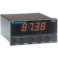
IDP-1 NEWPORT ELECTRONICS, IDP-1 Datasheet

IDP-1
Specifications of IDP-1
Related parts for IDP-1
IDP-1 Summary of contents
Page 1
... NEWPORT Electronics, Inc. ® ...
Page 2
... NEWPORT Electronics, Inc. ® ...
Page 3
MANUAL OBJECTIVES NOTES, WARNINGS and CAUTIONS • NOTE • WARNING • CAUTION • IMPORTANT NOTE CAUTION or WARNING: CAUTION, WARNING or IMPORTANT: PREFACE ...
Page 4
Section SEC 1 INTRODUCTION SEC 2 ABOUT THE METER SEC 3 GETTING STARTED SEC 4 CONFIGURING THE METER APPENDICES Table of Contents Page ...
Page 5
Figures Table List of Figures List of Tables Page Page ...
Page 6
NOTES ...
Page 7
UNPACKING QTY DESCRIPTION SECTION 1. INTRODUCTION ...
Page 8
SAFETY CONSIDERATIONS Note ...
Page 9
SECTION 2. ABOUT THE METER 2.1 FRONT OF THE METER METER DISPLAY: METER MODES: MENU Figure 2-1. Front Panel ¡ ...
Page 10
METER BUTTONS T-RST £/MAX #### £/MAX £/MAX £/TARE MENU RESET £/MAX VALLEY ™™™™ £/TARE £/TARE MENU RESET “PrSt” “VrSt” RESET ...
Page 11
BACK OF THE METER Figure 2-2. Connectors for ac-Power (Top) and dc-Power (Bottom) Table 2-1. Connector Description Connector Description ...
Page 12
BACK OF THE METER (Continued) Figure 2-3. dc-Power Connections 2.3 DISASSEMBLY ...
Page 13
... CHANGING CONFIGURATION JUMPERS Table 3- DIP Switches (Defaults in bold and italics) Removed: 24 volt excitation Removed: All buttons operable Installed: PEAK shows when £/MAX button is pushed Removed: Calibration disabled “rxx” “idP” £/MAX ...
Page 14
CHANGING CONFIGURATION JUMPERS (Continued) Figure 3- Jumpers 3.2 MOUNTING THE METER Figure 3-2. Meter - Exploded View PANEL CUTOUT ...
Page 15
MOUNTING THE METER (Continued) 3.3 CONNECTING SENSOR INPUT EXC COM SIG Figure 3-4. 3-Wire dc Voltage Input Connection NOTE: Dimensions in Millimeters (Inches) Figure 3-3. Panel Cut-Out RTN 2 0 10Vdc ...
Page 16
CONNECTING SENSOR INPUT (Continued) 0 10Vdc SIG LOW SOURCE Figure 3-5. 2-Wire dc Voltage Input Connections EXTERNAL SUPPLY Figure 3-6. 4-20 mA Input Connections RTN SIG ...
Page 17
CONNECTING SENSOR INPUT (Continued) Figure 3-7. 4-20 mA Transmitter Hook-Up Figure 3-8. dc Current Input Connections with Current Source HOLD RTN with Internal Excitation ...
Page 18
CONNECTING MAIN POWER Figure 3-9. Main Power Connections - POWER ~ ~ ~ Figure 3-10. Main Power Connections - Power Line Neutral FUSE EUROPE ...
Page 19
SECTION 4. CONFIGURING THE METER 4.1 SELECTING THE INPUT RANGE (INPT) MENU ¢/TARE ¢/TARE MENU “StOr” “InP” “dEc.P” ...
Page 20
SELECTING A DECIMAL POINT POSITION (DEC.P) MENU ¢/TARE ¢/TARE MENU “Stor” 4.3 SCALING THE METER “dEc.P” “ScAL” “LivE” “int” ...
Page 21
Internal Scaling MENU ¢/TARE £/MAX ¢/TARE MENU “9999” ¢/TARE MENU “0000” “0400” “rd2” “ScAL” “int” “rd1” £/MAX “2000 £/MAX “Stor” ¢/TARE ...
Page 22
Live Scaling MENU ¢/TARE £/MAX £/MAX ¢/TARE MENU £/MAX ¢/TARE MENU “Stor” “ScAL” “LivE” “rd2” “rd1” ...
Page 23
CHANGING THE METER S CALIBRATION CAUTION not necessary to calibrate a brand new meter, it arrives completely calibrated. The following procedure modifies the calibration of the meter. This procedure should only be performed by qualified personnel with ...
Page 24
CHANGING THE METER S CALIBRATION (Continued) MENU Table 4-1. Meter Calibration Table Range 0-10V 0-5, 1-5V 4-20, 20-4 mA £/MAX MENU “Stor” “rd2” Low Input rd1* 0 Vdc 0000 0 Vdc 0000 0 mA 0000 ¢/TARE Input High rd2* ...
Page 25
CHECKING AND CHANGING MAIN BOARD POWER JUMPERS IMPORTANT Figure A-1. 115Vac Jumper Wiring (Default) APPENDIX A JUMPER FOR 115Vac ...
Page 26
CHECKING AND CHANGING MAIN BOARD POWER JUMPERS JUMPER FOR 230Vac Figure A-2. 230 Vac Jumper Wiring APPENDIX A - (Continued) ...
Page 27
REFERENCE TABLES Table B-1. Display Messages MESSAGE 123* 123 PrSt VrST T-RST Table B-2. Menu Configuration Displays MENU InP DEC.P ScAL APPENDIX B DESCRIPTION ¢/TARE £ £/MAX ...
Page 28
APPENDIX B - REFERENCE TABLES (Continued) Display ¢/TARE PrST VrST T-RST ¢ Table B-4. Factory Preset Values Menu Item Description INPT DEC.P Sensor Excitation: Line Frequency: Table B-3. Run Mode Displays RESET £/MAX T-RST Jumpers ...
Page 29
SPECIFICATIONS Input Power Information: Environment: Mechanical APPENDIX C ...
Page 30
APPENDIX C - SPECIFICATIONS (Continued) 96.00 (3.780) TOP VIEW 1,5 R (.06) 4 PLCS 92,00 +0,81/-0,00 (3.622 +.032/-.000) PANEL CUTOUT Figure C-1. Meter Dimensions 48.00(1.890) 0.73 (18.67) 3.22 (81.7) 3.74 (95.0) MAX SIDE VIEW PANEL THICKNESS: 6,4 (.25) MAX 0,8 ...
Page 31
APPENDIX INFORMATION Note 1: *Measurements performed on circuits not directly connected to the Mains Supply (power). Maximum Line-to-Neutral working voltage 50Vac/dc. Note 2: This unit should not be used in Measurement Categories II, III, IV. ...
Page 32
INDEX ...
Page 33
INDEX ...
Page 34
Warranty/Disclaimer Return Requests/Inquiries ...
Page 35
K ...


