M135-0-0-24-0 Simpson, M135-0-0-24-0 Datasheet - Page 2
M135-0-0-24-0
Manufacturer Part Number
M135-0-0-24-0
Description
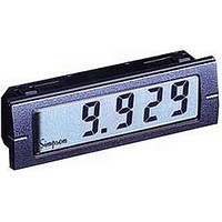
Current Meter
Manufacturer
Simpson
Type
Ammeterr
Specifications of M135-0-0-24-0
No. Of Digits / Alpha
3.1/2
Meter Function
DC Milliammeter
Meter Range
0mA To 200mA
Digit Height
12.7mm
Operating Temperature Range
0°C To +55°C
Meter Signal Input
Current
Meter Output
Current
Accuracy
±0.1% %
Bezel
0.945 in. x 2.835 in.
Brand/series
M135
Common Mode Rejection Ratio
90 dB (Min.) @ 60 Hz
Connection Type
Wire Leads
Current, Rating
200 mA
Cut Out, Panel
0.874×2.677 "
Depth
0.473 in.
Dimensions
2.84"L×0.43"W×0.945"H
Display Digit Height
0.5 "
Display Resolution
100 μA
Display Type
LCD
Function
Ammeter
Humidity
0 to 85%
Indicator Type
3-1⁄2 Digit
Material, Casing
ABS
Meter Type
Digital
Number Of Digits
3-1/2
Primary Type
Electronic
Range, Measurement
200 mA
Temperature, Operating
0 to 55 °C
Voltage Drop
200 mV
Voltage, Supply
5 VDC
Equipment Type
DC Current Meter
Leaded Process Compatible
No
Rohs Compliant
No
Lead Free Status / RoHS Status
Contains lead / RoHS non-compliant
Lead Free Status / RoHS Status
Contains lead / RoHS non-compliant


These instruments are designed for maximum safety
to the operator when mounted in a panel according
to instructions. They are not to be used unmounted
or for exploratory measurements
in unknown circuits.
A reversed polarity power supply will permanently
damage this instrument.
IN HIGH and IN LOW must remain within the limits of
the power supply breakdown voltage.
No internal isolation provided. Each meter requires
an isolated power supply. Supply voltage must
also be isolated from the circuit being measured.
A positive reading will be displayed when IN Hi is
more positive than IN Low.
Internal Reference: REFOUT must always be con-
nected to REFIN unless an external reference is
being used.
External Reference: Connect between REFIN and
ANALOG GROUND; REFOUT should then be uncon-
nected (open). For best results, external reference
voltage should be in the range of 50mV to 150mV.
System stability is then only as good as the external
reference.
Calibration
Model M135 has a limited range adjustment for cali-
bration. Apply the appropriate current input for a
near full scale reading, typically 1900 counts on the
display. The adjustment is accessed through the
exposed hole in the upper left corner of the rear
panel. For this adjustment to function, REFOUT must
be connected to REFIN.
Backlight Power Supply
A 2-pin connector is included with the unit if back-
lighting is specified. The right pin is the Positive, and
the left pin is for the Negative power supply. See the
Rear Connections diagram for location.
DISPLAY
Type: 7-segment LCD
Height: 0.5” (12.7mm)
Decimal point: 3-position programmable
Overrange indication: Most significant = “1”
Backlighting: Optional negative image, red
backlighting at 5, 10, 12, 24, or 48VDC
Polarity: Auto with “-” indication, “+” indication
implied
POWER REQUIREMENTS
DC Power: ±5V, +5V, and +9V
(Low battery indication provided with 9V units)
Power supply current: 2mA max
Backlight supply current: 50mA typical
For 24 and 48VDC, 10mA typical
ACCURACY @ 25°C:
±(0.1% of reading + 1 count
Connections
Safety Symbols
Specifications
The WARNING sign denotes a hazard. It
calls attention to a procedure, practice, or
the like, which, if not correctly performed
or adhered to, could result in personal
injury.
The CAUTION sign denotes a hazard. It
calls attention to an operating procedure,
practice, or the like, which, if not correct-
ly adhered to, could result in damage to
or destruction of part or all of the instru-
ment.
Input Signal
Input Signal
Input Signal
ENVIRONMENTAL
Operating Temperature: 0 to 55°C
Storage Temperature: -10 to 60°C
Relative Humidity: 0 to 85% non-condensing
Warmup time: Less than 20 minutes
Temperature Coefficient: (All inputs)
NOISE REJECTION
NMRR: 60dB, 50/60Hz
CMRR: (with 1KV unbalanced @ 60 Hz): 90dB min
ANALOG TO DIGITAL CONVERSION
Technique: Integrating
Rate: 3 samples/second-typical
MECHANICAL
Bezel: 0.945” x 2.835”
Basic Unit
In Low REFOUT Supply
In Hi
In Low REFOUT Supply
In Hi
In Hi
In Low REFOUT Supply
In Hi
In Low REFOUT Supply
M135
(0.2% of input
Ordering Information
(24mm x 72mm)
Mini Current Indicators can be configured by making an entry for each box
3-1/2 Digit Indicator
Ground
Ground
Ground
Ground
Analog
Analog
Analog
Analog
Positive
Ground
Positive
Ground
Ground
Ground
Supply Negative REFIN
Supply Negative REFIN
Supply Negative REFIN
Positive
Supply Negative
Positive
0.2 digit)/ C
0
1
9 VDC Power Supply
+5 VDC Power Supply
±5 VDC Power Supply
Optional Connections
Non Backlight
Negative Image Red
Supply
Supply
Supply
Supply
Display
Hold
Hold
Hold
Hold
REFIN
DP1
DP1
DP1
DP1
DPM Power Supply
DP2
DP3
DP2
DP2
DP3
DP3
DP2
DP3
0
1
2
Depth: 0.473” (12mm)
Panel cutout: 0.874” x 2.677”
Weight: 10oz (28.3g)
Case Material: 94-VO, UL-rated ABS
INPUTS: DC Current
+5VDC
±5VDC
+9VDC
200mA
Range
200 A
20mA
2mA
VDC
VDC
VDC
VDC
+5
-5
9
5
+
+
-
-
Decimal Point: DP 1 is the first decimal
point to the left of the least significant digit.
Connect DP# to Positive Supply to activate.
Unneeded features should remain uncon-
nected.
Display Hold: The display can be held
indefinitely by connecting Hold to Positive
Supply. The display will function normally
when this connection is removed.
Resolution
100 A
100 A
(22.2mm x 68mm)
10 A
1 A
21
22
23
24
Range
Rear Connections
DP3
Decimal Point
200mA
200 A
20mA
2mA
Mini M135
Voltage
200mV
200mV
200mV
200mV
Drop
DP2
DP1
0
1
2
3
4
5
Input (unfused)
Backlight Power
Maximum
100mA
400mA
10mA
40mA
10VDC
12VDC
24VDC
48VDC
5VDC
None
Related parts for M135-0-0-24-0
Image
Part Number
Description
Manufacturer
Datasheet
Request
R

Part Number:
Description:
Current Meter
Manufacturer:
Simpson
Datasheet:

Part Number:
Description:
3-1/2 LCD, 9VDCPWR, 200VDC
Manufacturer:
Simpson
Datasheet:

Part Number:
Description:
Voltage LED Display Panel
Manufacturer:
Simpson
Datasheet:

Part Number:
Description:
TYPE J FIXED IMMERSION THERMOCOUPLE
Manufacturer:
Simpson
Datasheet:

Part Number:
Description:
Voltage Meter
Manufacturer:
Simpson
Datasheet:
Part Number:
Description:
Voltage Meter
Manufacturer:
Simpson
Datasheet:
Part Number:
Description:
DIGITAL PANEL METER MODEL M135 WITH CERTIFICATE OF CALIBRATION
Manufacturer:
Simpson
Part Number:
Description:
Totalizer Display Panel
Manufacturer:
Simpson
Datasheet:
Part Number:
Description:
Analog Panel Meters 1349 0-50 ACV-RE
Manufacturer:
Simpson
Datasheet:
Part Number:
Description:
Analog Panel Meters 2121 25-0-25 DCUA
Manufacturer:
Simpson
Datasheet:
Part Number:
Description:
ANALOG FREQUENCY METER
Manufacturer:
Simpson
Datasheet:
Part Number:
Description:
TERMINAL,PIDG R 12-10 1/4
Manufacturer:
Simpson
Datasheet: