PAXC0000 Red Lion Controls, PAXC0000 Datasheet - Page 29
PAXC0000
Manufacturer Part Number
PAXC0000
Description
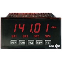
Multifunction Counter
Manufacturer
Red Lion Controls
Type
Counterr
Specifications of PAXC0000
No. Of Digits / Alpha
6
Signal Input Type
Pulse
Character Size
0.56"
Ip/nema Rating
IP65 / NEMA 4X
Panel Cutout Height
1.77"
Display Font Color
Red
Panel Cutout Width
3.62"
Connection Type
Cage-Clamp
Cut Out, Panel
1/8 DIN
Digit Height
1.5
Dimensions
4.2"L×3.8"W×1.95"H
Display Digit Height
0.56 "
Display Type
LED
Function
Counter
Indicator Type
Counter
Number Of Digits
6
Primary Type
Electronic
Range, Measurement
±99999999
Special Features
Programmable Function Keys
Temperature, Operating, Range
0 to 50 °C
Termination
Cage Clamp
Voltage, Supply
85 to 250 VAC
Counter Supply Voltage
85-250VAC
Rohs Compliant
Yes
Lead Free Status / RoHS Status
Lead free / RoHS Compliant


4. If the meter appears to be indicating incorrectly or inaccurately, refer to the
Troubleshooting section.
should be performed by qualified technicians using appropriate equipment.
Calibration does not change any user programmed parameters.
exiting Module 9. In this case, the existing calibration settings remain in effect.
Note: Allow a 30 minute warm-up period before staring calibration.
TROUBLESHOOTING
PAXI: CALIBRATION
When Analog Out recalibration is required (generally every 2 years), it
Calibration may be aborted by disconnecting power to the meter before
Shaded areas are model dependent.
PROBLEM
NO DISPLAY
PROGRAM LOCKED-OUT
CERTAIN DISPLAYS ARE LOCKED OUT
INCORRECT DISPLAY VALUE or NOT
COUNTING
USER INPUT NOT WORKING CORRECTLY
OUTPUT DOES NOT WORK
JITTERY DISPLAY
“
MODULES or PARAMETERS NOT ACCESSIBLE
ERROR CODE (
SERIAL COMMUNICATIONS
” RATE
is the Analog Output. The Count A and B values are scaled
using the parameters in Module 1, Counter C value is scaled
using Module 5 and the Rate value is scaled using Module
The only item in the PAXI meter that can be calibrated
For further assistance, contact technical support at the appropriate company numbers listed.
)
REMEDIES
CHECK: Power level, power connections
CHECK: Active (lock-out) user input
ENTER: Security code requested
CHECK: Module 3 programming
CHECK: Input wiring, DIP switch setting, input programming, scale factor calculation,
CHECK: User input wiring, user input jumper, user input being used for signal, Module 2
CHECK: Corresponding plug-in card installation, output configuration, output wiring
CHECK: Wiring is per EMC installation guidelines, input signal frequency, signal quality,
CHECK: Lower input signal frequency, reduce rate scaling
CHECK: Corresponding plug-in card installation, related controlling parameter selected
PRESS: Reset key (if unable to clear contact factory.)
CHECK: Wiring, connections, meter and host settings
input signal level, user input jumper, lower input signal frequency
scaling, update time, DIP switch setting
29
Analog Output Card Calibration
better (voltmeter for voltage output and/or current meter for current output) is
connected and ready. Then perform the following procedure:
1. Use the arrow keys to display
2.
3. Using the chart below, step through the five selections to be calibrated. At
Before starting, verify that a precision meter with an accuracy of 0.05% or
each prompt, use the PAXI arrow keys to adjust the output so that the
external meter display matches the selection being calibrated. When the
external reading matches, or if the range is not being calibrated, press PAR.
4. When
SELECTION
is displayed. Use the arrow keys to select
appears, press PAR twice and remove the external meters.
EXTERNAL METER
20.00
10.00
0.00
4.00
0.00
and press PAR.
Adjust if necessary, press PAR
Adjust if necessary, press PAR
Adjust if necessary, press PAR
Adjust if necessary, press PAR
Adjust if necessary, press PAR
and press PAR.
ACTION
Related parts for PAXC0000
Image
Part Number
Description
Manufacturer
Datasheet
Request
R

Part Number:
Description:
Counter
Manufacturer:
Red Lion Controls
Datasheet:
Part Number:
Description:
Miniature Length Sensor
Manufacturer:
Red Lion Controls
Datasheet:
Part Number:
Description:
Model Lsc - Single Channel Output Length Sensor
Manufacturer:
Red Lion Controls
Datasheet: