AND-TFT-5VX-KIT AND DISPLAYS, AND-TFT-5VX-KIT Datasheet - Page 5
AND-TFT-5VX-KIT
Manufacturer Part Number
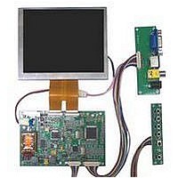
AND-TFT-5VX-KIT
Description
LCD COLOR MONITOR 640X480
Manufacturer
AND DISPLAYS
Datasheet
1.AND-TFT-5VX-KIT.pdf
(11 pages)
Specifications of AND-TFT-5VX-KIT
Signal Input Type
NTSC, PAL, TFT Analog VGA
Rohs Compliant
Yes


CN 2
Note 1: Gate off voltage, V
Note 2 : Gate on voltage, V
Note 3 : Select up or down shift ( see Table 1 )
Note 4 : Gate driver shift clock
Note 5 : When OE is connected to high “1”, the driver outposts
Note 6 : Select left or right shift ( see Table 2 )
Note 7 : Latch the polarity of outputs and switch the new data
Note 8 : Control whether the Data RO~G5 are inverted or not.
Note 9 : Polarity selector for dot-inversion control. Available
05/13/03
Pin #.
10
11
12
13
14
15
16
17
18
19
20
21
22
23
24
25
26
27
28
29
30
1
2
3
4
5
6
7
8
9
are disabled (Gate output=V
the operation of registers will not be affected.
to outputs. At the rising edge (LD), latch the “POL”
signal to control the polarity of the outputs.
(PVI suggests connecting to GND) When “REV=1”
“38”, “15” to “2A”
at the rising edge of LD. When POL=1: Even outputs
range from V1~V7, and Odd outputs range from
V8~V14, and Odd outputs range from V1~V7.
these data will be inverted. EX: “00” to “3F”, “07” to
Displays
Tel: 408.523.8200 • Fax: 408.733.1287 • sales@purdyelectronics.com • www.purdyelectronics.com
Symbol
VCOM
VSS2
VSS2
VSS2
VDD2
STVU
STVD
XON
VGG
GND
VCC
GND
CKV
VEE
V10
V11
V12
V13
V14
U/D
OE
V1
V2
V3
V4
V5
V6
V7
V8
V9
Purdy Electronics Corporation • 720 Palomar Avenue • Sunnyvale, CA 94085
EE
GG
I/O
=10V.
=19V.
|
I
I
I
I
I
I
I
I
I
I
I
I
I
I
I
I
I
I
I
I
I
I
I
I
I
I
I
I
I
EE
Ground
Gamma Voltage 1
Gamma Voltage 2
Gamma Voltage 3
Gamma Voltage 4
Gamma Voltage 5
Gamma Voltage 6
Gamma Voltage 7
Ground
Gamma Voltage 8
Gamma Voltage 9
Gamma Voltage 10
Gamma Voltage 11
Gamma Voltage 12
Gamma Voltage 13
Gamma Voltage 14
Ground
Voltage for analog circuit
Common Voltage
NC
Output Enable
Right / Left Selection
Vertical Shift Cllock
Vertical Shift Pulse Signal Input or Output
Vertical Shift Pulse Signal Input or Output
Gate On Voltage
Ground
Voltage for logic circuit
Ground
Gate Off Voltage
). Under this condition,
Function
Table 2
Table 1
R / L
U / D
1
0
1
0
STVU
D | O2
Input
Input
Hi-Z
Hi-Z
STVD
D|O2
Input
Input
Hi-Z
Hi-Z
AND-TFT-5VX-KIT
Remark
Note 5
Note 3
Note 4
Note 3
Note 3
Note 2
Note 1
Left to Right
Right to Left
Down to Up
Up to Down
Shift
Shift
5
Related parts for AND-TFT-5VX-KIT
Image
Part Number
Description
Manufacturer
Datasheet
Request
R

Part Number:
Description:
Display, Color, LCD, 3.5" Diag., 640 + 480, 5 V, Analog VGA/NTSC/PAL, Proto Kit
Manufacturer:
AND / Purdy Electronics
Datasheet:
Part Number:
Description:
Display, Color, LCD, 5" Diag., 640 + 480, 12 V, Analog VGA/NTSC/PAL, Proto Kit
Manufacturer:
AND / Purdy Electronics
Datasheet:
Part Number:
Description:
Display, Color, LCD, 5" Diag., 320 + 234, 12 V, NTSC/PAL, Prototyping Kit
Manufacturer:
AND / Purdy Electronics
Datasheet:
Part Number:
Description:
Display, Color, LCD, 6.4" Diag., 320 + 234, 12 V, NTSC/PAL
Manufacturer:
AND / Purdy Electronics
Datasheet:
Part Number:
Description:
Display, Color, LCD, 5" Diag., 640 + 480, 12 V, NTSC/PAL/VGA
Manufacturer:
AND / Purdy Electronics

Part Number:
Description:
COLOR TFT MONITOR 640X480
Manufacturer:
AND DISPLAYS
Datasheet:

Part Number:
Description:
LCD Display Panel
Manufacturer:
AND DISPLAYS
Datasheet:
Part Number:
Description:
LCD Display Panel
Manufacturer:
AND DISPLAYS
Datasheet:
Part Number:
Description:
COLOR TFT MONITOR 320X234
Manufacturer:
AND DISPLAYS
Datasheet:
Part Number:
Description:
3.5" TFT 640X480 HB VGA Prototyping Kit
Manufacturer:
AND DISPLAYS
Part Number:
Description:
3.5" TFT 320X234 Video Prototyping Kit
Manufacturer:
AND DISPLAYS

Part Number:
Description:
LCD Module Kit
Manufacturer:
AND DISPLAYS
Datasheet:
Part Number:
Description:
LCD Display Panel
Manufacturer:
AND DISPLAYS
Datasheet: