OEM33 ANDERS ELECTRONICS, OEM33 Datasheet - Page 2
OEM33
Manufacturer Part Number
OEM33
Description
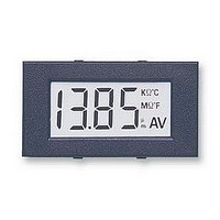
DPM, LCD, 3.5DIGIT, MINI
Manufacturer
ANDERS ELECTRONICS
Datasheet
1.OEM33.pdf
(3 pages)
Specifications of OEM33
Supply Voltage Range
7V To 10V, 4.5V To 6V
No. Of Digits / Alpha
3.1/2
Display Size
30mm X 14mm
Panel Cutout Height
22mm
Panel Cutout Width
41m
Operating Temperature Range
0°C To +50°C
Display
RoHS Compliant
Accuracy
± 0.1%
Rohs Compliant
Yes


The OEM33 is designed for 5/9V supply. Incorrect supply
polarity will destroy the module immediately. It is ready
for general use when connected as in fig. 1 for 5V. For 9V
supply the module may need calibrating before use as
follows. Connect as in fig. 2, apply 100mV to the inputs
from a calibrated source and adjust VR1 until the display
reads 1000.The input range is 0-199.9mV.Over-range is
indicated by displaying a "1" in the most significant digit. If
the input voltage is reversed, a minus sign is displayed
automatically.
The module has 3 decimal points. D1, D2, D3 and 11
selectable annnunciators.
For 5V operation, IL must be connected to GD for
non-floating inputs (fig. 1) and to analogue common pin C
for floating inputs. In both cases J1 should be closed).
DC VOLTAGE MEASUREMENT
DC CURRENT MEASUREMENT
NON FLOATING INPUTS (a)
DC VOLTAGE OFFSET
USER INSTRUCTIONS
APPLICATION CIRCUITS
Revision - 14 27/08/04
The input impedance becomes R1+R2. Choose accurate stable
resistors. Typically, R1=1MΩ. 9MΩ is a practical upper limit.
To measure voltages greater than 200mV
an attenuator is required. First choose R1.
EXAMPLES
10V 1500rpm
V
2V
R2= x
IN
anders
Where a single 5V supply is not
suitable but you must connect your
input signal ground to the module
supply ground then either of the two
non-floating input circuits can be used.
Note that the module is set in 9V
supply mode BUT jumper J1 is left
open.
Shunt resistance
It is important to note the power
dissipation in the shunt and choose
resistor rating accordingly
Display
1.999V
EXAMPLES
(Vin/Vd)-1
To achieve a zero display reading
for a non-zero voltage input,
apply the offset voltage between
C and IL.
For a positive offset apply a
Positive signal to IL w.r.t. C.
Apply the input signal between
IH and C
Note jumper J1 must be open
P
Tel: +44 (0)20 7380 8167 Fax: +44 (0)20 7874 1908
R1
S
Current
=
200mV
2A
Vs
I
IN
electronics plc
199.9mV 1MΩ 110KΩ
2
150mV
= I
V
V
D
IN
D
0.1Ω
2
1Ω
R
max. is 199.99mV
R
R
S
S
S
1MΩ
=
R1
Ω
Vs
I
0.04W
IN
0.4W
P
Ω
15KΩ
S
R2
Bayham Place, London NW1 OEU UK
For 9V operation it is recommended to power from a 9V
battery. The inputs are intended to float with respect to the
supply but if they do not float they must be no closer than
1.5V from either VDD or VSS (VDD-1.5V and VSS+1.5V)
see the circuits for non-floating inputs below.
DC MULTI-RANGE CURRENT MEASUREMENT
NON FLOATING INPUTS (b)
DC MULTI-RANGE VOLTAGE MEASUREMENT
DC VOLTAGE RATIO MEASUREMENT
CONNECTION DIAGRAM
www.anders.co.uk
Using the formulae choose resistors to
ensure the analogue inputs are no
closer than 1.5V from either VDD or
VSS (VDD-1.5V or VSS+1.5V)
To determine the ratio between two
voltages apply the inputs as shown.
Displayed reading
Over range occurs when
Note Jumper J1 must be closed and
the track connecting RL to C must be
cut
BASIC CONFIGURATION
For multi-range, use a 2 pole,
4 way rotary switch. 1 pole for
range select and the other to
connect the appropriate
decimal point to XBP.
For multi-range, use, a 2 pole,
5 way rotary switch. 1 pole for
range select and the other to
connect the appropriate
decimal point to XBP
=
V2
V1
X 1000
V2
V1
>
2
Related parts for OEM33
Image
Part Number
Description
Manufacturer
Datasheet
Request
R

Part Number:
Description:
SCALE, 78X60, PM, 0-100
Manufacturer:
ANDERS ELECTRONICS
Datasheet:
Part Number:
Description:
SCALE, 96X75, PM, 0-100
Manufacturer:
ANDERS ELECTRONICS
Datasheet:

Part Number:
Description:
BEZEL, OEM22/24L
Manufacturer:
ANDERS ELECTRONICS
Datasheet:

Part Number:
Description:
DPM, LED, DIN, DC VOLTMETER
Manufacturer:
ANDERS ELECTRONICS
Datasheet:
Part Number:
Description:
DPM, LED, DIN, AC VOLTMETER
Manufacturer:
ANDERS ELECTRONICS
Datasheet:

Part Number:
Description:
DPM, LCD, 4-20MA, PROCESS
Manufacturer:
ANDERS ELECTRONICS
Datasheet:

Part Number:
Description:
DPM, LCD, THERMOMETER
Manufacturer:
ANDERS ELECTRONICS
Datasheet:
Part Number:
Description:
DPM, LCD
Manufacturer:
ANDERS ELECTRONICS
Datasheet:

Part Number:
Description:
METER, 78X60, 0-1MA
Manufacturer:
ANDERS ELECTRONICS
Datasheet:
Part Number:
Description:
METER, 78X60, 0-100UA
Manufacturer:
ANDERS ELECTRONICS
Datasheet:
Part Number:
Description:
METER, 96X75, 0-1MA
Manufacturer:
ANDERS ELECTRONICS
Datasheet:

Part Number:
Description:
AMP METER
Manufacturer:
ANDERS ELECTRONICS
Datasheet:

Part Number:
Description:
METER, CIRCULAR, 0-200UA
Manufacturer:
ANDERS ELECTRONICS
Datasheet:

Part Number:
Description:
METER, CIRCULAR, 0-200UA
Manufacturer:
ANDERS ELECTRONICS
Datasheet:

Part Number:
Description:
METER, MOVING, COIL, 0-100UA
Manufacturer:
ANDERS ELECTRONICS
Datasheet: