DPM125-BL LASCAR, DPM125-BL Datasheet - Page 2
DPM125-BL
Manufacturer Part Number
DPM125-BL
Description
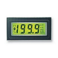
LCD MODULE, 3.5DIGIT
Manufacturer
LASCAR
Datasheet
1.DPM125-BL.pdf
(4 pages)
Specifications of DPM125-BL
Supply Voltage Range
7.5VDC To 14VDC
No. Of Digits / Alpha
3.1/2
Display Size
31mm X 14mm
Panel Cutout Height
22.2mm
Panel Cutout Width
45mm
Operating Temperature Range
0°C To +50°C
Svhc
No SVHC
Accuracy
0.1% ±
Rohs Compliant
Yes
Lead Free Status / RoHS Status
Lead free / RoHS Compliant


SCALING
Two resistors may be used to alter the full scale reading of the meter - see table.
Note that the meter will have to be re-calibrated by adjusting the calibration pot .
SAFETY
To comply with the Low Voltage Directive (LVD 93/68/EEC), input voltages to the module’s pins must not exceed 60Vdc. If
voltages to the measuring inputs do exceed 60Vdc, then fit scaling resistors externally to the module. The user must ensure that
the incorporation of the DPM into the user’s equipment conforms to the relevant sections of BS EN 61010 (Safety Requirements
for Electrical Equipment for Measuring, Control and Laboratory Use).
PIN FUNCTIONS
VARIOUS OPERATING MODES
ON-BOARD LINKS: In order to quickly and easily change operating modes for different
applications, the meter has several on-board links. They are designed to be easily cut
(opened) or shorted (soldered).
Do not connect more than one meter to the same power supply if the meters cannot use the
same signal ground. Taking any input beyond the power supply rails will damage the meter.
Unless otherwise noted, specifications apply at TA=25°C, Vsupply=9Vd.c. (5Vd.c. for 'S' versions) (fclock=48kHz) and
are tested with the module configured for fully floating input mode.
10. RLO
11. RHI
12. ROH
10. REF LO Negative input for reference voltage.
11. RHI
12. ROH
13. LMP-
14. LMP+ Positive backlight power supply connection.
1. DP1
2. DP2
3. DP3
4. TEST
5. V-
6. V+
7. IN HI
8. INLO
9. COM
199.9
19.99
1.999
Connect to V+ to display segments as illustrated. It should not be operated for more than a few seconds as the
d.c. voltage appliedto the LCD may 'burn' the display. This pin is normally at 5V below V+ and is the ground for
the digital section of the meter. It can be used to power external logic up to a maximum of 1mA.
Negative power supply connection.
Positive power supply connection.
Positive measuring differential input.
Negative measuring differential input.
The ground for the analogue section of the A/D converter, held actively at 2.8V (nom.) below V+. COM must
not be allowed to sinkexcessive current (>100 A) by connecting it directly to a higher voltage.
Negative input for reference voltage (can be connected to COM via Link 3).
Positive input for reference voltage (connected via Link 1 to ROH).
Positive output from internal reference.
Positive input for reference voltage (connected via Link 1 to ROH).
Positive output from internal reference.
Negative backlight power supply connection.
Connect to V+ to display required DP .
This compact LCD DPM uses advanced components and construction techniques to provide an
unrivalled combination of high performance and low cost. For poor visibility, a long life LED
backlight is fitted.
• 12.5mm (0.5“) Digit Height
• Logic Selectable Decimal Points
• Auto-zero
Analogue inputs must be no closer than 1V to either
the positive or negative supply
2
• Auto-polarity
• 200mV d.c Full Scale Reading (F.S.R.)
• LED Backlighting
Normally SHORTED
Cut to OPEN
Normally OPEN
Solder to SHORT
Measuring a floating voltage source of 200mV full scale.
Mesure d’un voltage flottant de 200mV pleine échelle.
Messung einer potentialfreien Spannung mit 200 mV Vollausschlag.
Misurazione di una sorgente di tensione oscillante di 200mV in grandezza
naturale.
Measuring current. Supply MUST be isolated.
Mesure de courant. L’alimentation DOIT être isolée.
Strommessung. Versorgung muß elektrisch getrennt sein.
Misurazione della corrente. L’alimentazione DEVE essere isolata.
APPLICATIONS
APPLICATIONS
R=
+
-
FSR
0.2
R
10
7
8
9
10
8
9
7
IN HI
IN LO
COM
REF LO
IN LO
COM
REF LO
IN HI
V+
V-
6
5
V-
V+
Measuring a single ended input reference to supply ground.
* Input voltage
Mesure d’une entrée à connexion unique référencée à l’alimentation.
* Tension d'alimentation
Messen eines auf die Versorgung bezogenen massebezogenen Eingangs.
* Eingangsspannung
Misurazione di un ingresso con polo in comune rispetto all'alimentazione.
* Tensione d'ingresso
5
6
V+
V-
V-
V+
10 F
+
-
4
*
2
7660
+
V+
-
5
8
3
+
-
7
7
8
10 F
ANWENDUNGEN
ESEMPI DI MODALITA' DI FUNZIONAMENTO
Check Links 1 & 2 are OPEN.
Measuring the ratio of two voltages.
Reading = 1000 V /V
50mV< V <200mV
V <2V
Vérifier que les liaisons 1 & 2
sont OUVERTES.
Mesure du ratio de deux voltages
Lecture = 1000V /V
50mV<V <200mV
V <2V
IN HI
IN LO
1
1
2
2
V-
Measuring 4-20mA to read 0-999. (supply MUST be isolated).
Mesure de 4-20mA pour lire 0-999. (L’alimentation DOIT être isolée).
Messung von 4 - 20 mA bei Anzeige 0 - 999.
(Versorgung muß elektrisch getrennt sein.)
Misurazione di 4-20mA per leggere 0-999.
(l’alimentazione DEVE essere isolata).
6
5
2
2
+5V
1
1
6R2
2
2
OUT
IN
V
V
1
2
5K
+
+
-
-
10
11
SET
ZERO
220K
8
7
IN LO
REF HI
REF LO
IN HI
10
9
7
8
IN HI
IN LO
COM
REF LO
Spannungsverhältnisses.
1 e 2 siano APERTI.
Misurazione del rapporto delle
due tensioni.
Lettura = 1000 V1/V2
50mV <V <200mV
V <2V
V+
V-
Überprüfen Sie, daß Brücke 1 u. 2
OFFEN sind.
Messung eines
Meßwert = 1000 V /V
50 mV < V < 200 mV
V < 2 V
Controllare che i collegamenti
1
1
6
5
V-
V+
V-
2
V+
6
5
2
2
V+
2
V-
1
2
Related parts for DPM125-BL
Image
Part Number
Description
Manufacturer
Datasheet
Request
R

Part Number:
Description:
DPM, LED, 3.5DIGIT
Manufacturer:
LASCAR
Datasheet:

Part Number:
Description:
DPM, LCD, 3.5DIGIT, MINI
Manufacturer:
LASCAR
Datasheet:

Part Number:
Description:
DPM, LCD, 4.5DIGIT, MINI
Manufacturer:
LASCAR
Datasheet:

Part Number:
Description:
DPM, LCD, 3.5DIGIT
Manufacturer:
LASCAR
Datasheet:
Part Number:
Description:
DPM, LCD, 3.5DIGIT, NEGATIVE RAIL
Manufacturer:
LASCAR
Datasheet:

Part Number:
Description:
DPM, LCD, 3.5DIGIT
Manufacturer:
LASCAR
Datasheet:
Part Number:
Description:
DPM, LCD, 3.5DIGIT
Manufacturer:
LASCAR
Datasheet:
Part Number:
Description:
DPM, LCD, 3.5DIGIT, NEGATIVE RAIL
Manufacturer:
LASCAR
Datasheet:

Part Number:
Description:
Voltage Meter
Manufacturer:
LASCAR
Datasheet:

Part Number:
Description:
VOLTMETER, LCD, 3.5DIGIT, 35MM
Manufacturer:
LASCAR
Datasheet:

Part Number:
Description:
VOLTMETER, LCD, 3.5DIGIT, 40MM
Manufacturer:
LASCAR
Datasheet:

Part Number:
Description:
VOLTMETER, LED, 3.5DIGIT, RED
Manufacturer:
LASCAR
Datasheet:

Part Number:
Description:
Voltage Meter
Manufacturer:
LASCAR
Datasheet:

Part Number:
Description:
Status Indicator
Manufacturer:
LASCAR
Datasheet:

Part Number:
Description:
Power Supply, Benchtop, 1.5 - 30Vdc (0-1 Amp)
Manufacturer:
Lascar Electronics
Datasheet: