PGMMOD00 Red Lion Controls, PGMMOD00 Datasheet - Page 4
PGMMOD00
Manufacturer Part Number
PGMMOD00
Description
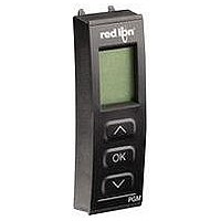
Display Programming Module
Manufacturer
Red Lion Controls
Datasheet
1.PGMMOD00.pdf
(12 pages)
Specifications of PGMMOD00
Accessory Type
Display Programming Module
Module Type
Programming/Display
For Use With
IAMS Universal Signal Conditioning Modules
Lead Free Status / RoHS Status
Lead free / RoHS Compliant


be installed in a location that does not exceed the maximum operating
temperature and provides good air circulation. Placing the unit near devices that
generate excessive heat should be avoided.
WIRING OVERVIEW
sides of the unit. All conductors should conform to the unit’s voltage and current
ratings. All cabling should conform to appropriate standards of good
installation, local codes, and regulations. It is recommened that power supplied
to the unit (DC or AC) be protected by a fuse or circuit breaker.
those shown in wiring drawings for proper wire position. Insert the wire under
the correct screw-clamp terminal and tighten until the wire is secure. (Pull wire
to verify tightness.)
EMC INSTALLATION GUIDELINES
ElectroMagnetic Interference (EMI), proper installation and wiring methods
must be followed to ensure compatibility in each application. The type of the
electrical noise, source or coupling method into the unit may be different for
various installations. The unit becomes more immune to EMI with fewer I/O
connections. Cable length, routing, and shield termination are very important
and can mean the difference between a successful installation or troublesome
installation.
industrial environment.
1. Use shielded (screened) cables for all Signal and Control inputs. The shield
1.0 I
2.0 I
3.0 W
The IAMS is designed to mount to a top hat profile DIN rail. The unit should
The PGMMOD, Programming/Display Module is designed to connect to the
front of the IAMS. Insert the top of the programming module first, then allow
the bottom to lock into the IAMS.
When programming is complete, leave the programming module in place to
display the process data or press the release tab on the bottom of the
programming module.
Electrical connections are made via screw-clamp terminals located on the
When wiring the unit, compare the numbers on the terminal blocks against
Although this unit is designed with a high degree of immunity to
Listed below are some EMC guidelines for successful installation in an
(screen) pigtail connection should be made as short as possible. The
connection point for the shield depends somewhat upon the application.
Listed below are the recommended methods of connecting the shield, in order
of their effectiveness.
a. Connect the shield only at the rail where the unit is mounted to earth
b. Connect the shield to earth ground at both ends of the cable, usually when
c. Connect the shield to common of the unit and leave the other end of the
ground (protective earth).
the noise source frequency is above 1 MHz.
shield unconnected and insulated from earth ground.
NSTALLING THE
NSTALLING THE
IRING THE
U
NIT
U
P
ROGRAMMING
NIT
4
2. Never run Signal or Control cables in the same conduit or raceway with AC
3. Signal or Control cables within an enclosure should be routed as far away as
4. In extremely high EMI environments, the use of external EMI suppression
5. Long cable runs are more susceptible to EMI pickup than short cable runs.
6. Switching of inductive loads produces high EMI. Use of snubbers across
power lines, conductors feeding motors, solenoids, SCR controls, and
heaters, etc. The cables should be run in metal conduit that is properly
grounded. This is especially useful in applications where cable runs are long
and portable two-way radios are used in close proximity or if the installation
is near a commercial radio transmitter.
possible from contactors, control relays, transformers, and other noisy
components.
devices, such as ferrite suppression cores, is effective. Install them on Signal
and Control cables as close to the unit as possible. Loop the cable through the
core several times or use multiple cores on each cable for additional
protection. Install line filters on the power input cable to the unit to suppress
power line interference. Install them near the power entry point of the
enclosure. The following EMI suppression devices (or equivalent) are
recommended:
Therefore, keep cable runs as short as possible.
inductive loads suppresses EMI.
Ferrite Suppression Cores for signal and control cables:
Line Filters for input power cables:
Note: Reference manufacturer’s instructions when installing a line filter.
Snubber: RLC#SNUB0000.
Fair-Rite # 0443167251 (RLC #FCOR0000)
TDK # ZCAT3035-1330A
Steward #28B2029-0A0
Schaffner # FN610-1/07 (RLC #LFIL0000)
Schaffner # FN670-1.8/07
Corcom #1VR3
M
ODULE
Related parts for PGMMOD00
Image
Part Number
Description
Manufacturer
Datasheet
Request
R

Part Number:
Description:
Counter
Manufacturer:
Red Lion Controls
Datasheet:
Part Number:
Description:
Miniature Length Sensor
Manufacturer:
Red Lion Controls
Datasheet:
Part Number:
Description:
Model Lsc - Single Channel Output Length Sensor
Manufacturer:
Red Lion Controls
Datasheet: