GSM4+PSU2 MULTICOMP, GSM4+PSU2 Datasheet - Page 5
GSM4+PSU2
Manufacturer Part Number
GSM4+PSU2
Description
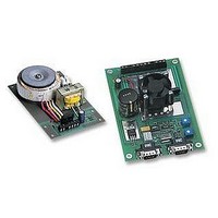
DRIVE, STEPPER MOTOR, 1.5A
Manufacturer
MULTICOMP
Datasheet
1.GSM4PSU2.pdf
(12 pages)
Specifications of GSM4+PSU2
Supply Voltage Range
240VAC
Output Voltage Max
40VDC
Output Current
800mA
External Depth
150mm
External Length / Height
35mm
External Width
100mm
For Use With
Motor And Controller Testing


GSM4MAN
Page 5 of 12
For example if the motor winding recommended current is 1.5 Ampere then the pot 2 should be adjusted to read
500mV. Warning ! Under no circumstances connect a meter set to Ohms Range, or any other voltage source,
across R ref., as this will destroy the motor drive controller. Limit and motor enable switches may be connected
to the GSM4. If the motor enable switch is NOT used the appropriate terminal on the GSM4 must be linked to
OV logic.
SERIAL PORT SETUP (COM 1)
9600 Baud
8 Bits
No Parity
1 Stop Bit
DEFAULT SETTINGS
On power up the GSM4 sets to the following default settings.
Full step mode. - 100% motor current option OFF.
No Ramp. - Motor current ON when stopped. Current boost for ramp OFF.
WARNINGS AND SAFETY INFORMATION
1/. Stepper motors get very HOT!
2/. Ensure motors are not over driven! Refer to motor specification.
3/. Ensure the GSM4 and PSU4 are well ventilated.
4/. DO NOT disable the GSM4 fan.
5/. DO NOT connect or disconnect the motor with power supplied to the GSM4
6/. Stepper motors generate high “Back EMF” voltages. Allow time for the magnetic fields to decay before
disconnecting motors.
7/. The MAXIMUM motor drive voltage is 40 V. DO NOT exceed 40 VOLTS.
8/. Ensure the mains input is adequately fused. The recommended mains input fuse rating is 250mA Slow
Blow.
9/. The GSM4 and stepper motors generate RF frequencies, appropriate screening is recommended.
10/. DO NOT connect a meter set to Ohms Range to the Reference resistors.
USING CONTROL PROGRAMME
file://C:\www1\gsm4man.html
25/03/02
Related parts for GSM4+PSU2
Image
Part Number
Description
Manufacturer
Datasheet
Request
R

Part Number:
Description:
IC, LINEAR VOLTAGE REGULATOR, 15V, TO-92
Manufacturer:
MULTICOMP
Datasheet:

Part Number:
Description:
Switch Cap
Manufacturer:
MULTICOMP
Datasheet:


Part Number:
Description:
COAXIAL CABLE, 100MM, BLACK
Manufacturer:
MULTICOMP
Datasheet:

Part Number:
Description:
FUSE, PTC RESET, 16V, 3A, RADIAL
Manufacturer:
MULTICOMP
Datasheet:
Part Number:
Description:
FUSE, PTC RESET, 16V, 4A, RADIAL
Manufacturer:
MULTICOMP
Datasheet:
Part Number:
Description:
FUSE, PTC RESET, 16V, 5A, RADIAL
Manufacturer:
MULTICOMP
Datasheet:

Part Number:
Description:
FUSE, PTC RESET, 30V, 1.85A, RADIAL
Manufacturer:
MULTICOMP
Datasheet:

Part Number:
Description:
FUSE, PTC RESET, 30V, 4A, RADIAL
Manufacturer:
MULTICOMP
Datasheet:
Part Number:
Description:
FUSE, PTC RESET, 30V, 8A, RADIAL
Manufacturer:
MULTICOMP
Datasheet:

Part Number:
Description:
FUSE, PTC RESET, 60V, 170mA, RADIAL
Manufacturer:
MULTICOMP
Datasheet:

Part Number:
Description:
FUSE, PTC RESET, 90V, 200mA, RADIAL
Manufacturer:
MULTICOMP
Datasheet:
Part Number:
Description:
FUSE, PTC RESET, 90V, 250mA, RADIAL
Manufacturer:
MULTICOMP
Datasheet:
Part Number:
Description:
FUSE, PTC RESET, 90V, 400mA, RADIAL
Manufacturer:
MULTICOMP
Datasheet:
Part Number:
Description:
FUSE, PTC RESET, 90V, 900mA, RADIAL
Manufacturer:
MULTICOMP
Datasheet:

Part Number:
Description:
FUSE, PTC RESET, 90V, 1.6A, RADIAL
Manufacturer:
MULTICOMP
Datasheet:
Part Number:
Description:
FUSE, PTC RESET, 90V, 1.85A, RADIAL
Manufacturer:
MULTICOMP
Datasheet:

Part Number:
Description:
FUSE, PTC RESET, 16V, 750mA, SMD
Manufacturer:
MULTICOMP
Datasheet:
Part Number:
Description:
FUSE, PTC RESET, 33V, 1.5A, SMD
Manufacturer:
MULTICOMP
Datasheet:
Part Number:
Description:
FUSE, PTC RESET, 33V, 1.85A, SMD
Manufacturer:
MULTICOMP
Datasheet: