RSE4812-B CARLO GAVAZZI, RSE4812-B Datasheet - Page 4
RSE4812-B
Manufacturer Part Number
RSE4812-B
Description
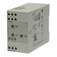
Motor Starter Relay
Manufacturer
CARLO GAVAZZI
Datasheet
1.RSE4812-B.pdf
(4 pages)
Specifications of RSE4812-B
No. Of Phases
Three
Power Rating
5.5kW
Current Rating
12A
Operating Temperature Range
-20°C To +50°C
Supply Voltage Max
480VAC
Control Voltage Max
110V
Control Voltage Min
24V
Supply Voltage Min
277VAC
Supply Voltage Range
277VAC To 480VAC


Applications
4
RSE 22 .. - B, RSE 4. .. - B, RSE 60 .. - B
Time between rampings
To prevent the semiconduc-
tors from overheating, a cer-
tain time between ramping
should be allowed. The time
between rampings depends
on the motor current during
ramping and ramp time (see
tables below).
RSE .. 03 - B
Time between rampings
RSE .. 12 - B
Time between rampings
Recommended thermal-magnetic overload relay
Selection Chart
Thermal-magnetic overload relay and motor controller
Example:
Line voltage: 230/400 V
Motor 1.5 HP: 1.1 kW
Full load current: 2.9 A
Motor full load current (AACrms)
Overload relay type GV 2-
Manufacturer: Telemecanique
Overload relay type MS 325-
Manufacturer: ABB
Motor protection circuit breaker type KTA 3-25-
Manufacturer: Allan-Bradley/Sprecher + Schuh
Motor controller type:
127/220 V mains
230/400 V mains
270/480 V mains
400/690 V mains
I ramp (A)
I ramp (A)
Ramp time (sec.)
Ramp time (sec.)
1.5
18
15
12
72
60
48
36
24
12
9
6
3
6
2.5 min 5 min 40 min
1.5 min 3 min 13 min 17 min
15 sec 30 sec 1.5 min 2.5 min
12 sec 20 sec 60 sec 1.5 min
10 sec 20 sec 50 sec 70 sec
50 sec 1.5 min 5 min 10 min
30 sec
15 sec 40 sec 1.5 min 2.5 min
10 sec 20 sec 50 sec 70 sec
8 sec
5 sec
2 sec
1 sec
5 sec
1
1
Note:
Table is valid for ambient
temperature 25°C. For higher
ambient
5%/°C to values in the tables.
The shaded areas in the ta-
bles are for blocked rotor. Do
not repeat rampings with
blocked rotor.
Step 1:
Select overload relay:
In this example GV 2 - M 08,
MS 325 - 4 or KTA 3-25-4A
must be used.
12 sec 30 sec 50 sec
9 sec
5 sec
2 sec
1 min
9 sec
2
2
temperature
25 sec 40 sec
20 sec 35 sec
20 sec 40 sec
5 sec
3 min
M 01 M 02 M 03 M 04 M 05 M 06 M 07 M 08 M 10 M 14 M 16
5
5
0.1 -
0.16
0.16
0.16
7 min
5 sec
0.16 - 0.25 - 0.4 -
0.25
0.25
0.25
N/A
10
10
add
0.4
0.4
0.4
Fusing Considerations
The motor controller provides
by-passing of the semicon-
ductors during running opera-
tion. Therefore the semicon-
ductors can only be damaged
by short-circuit currents dur-
ing ramp-up and ramp-down
function.
A 3-phase induction motor
with correctly installed and
adjusted overload protection
does not short totally between
lines or directly to earth as
some other types of loads,
e.g. heater bands. In a failing
motor there will always be
some part of a winding to limit
Step 2:
Select motor controller:
For line voltage 230/400 V and
overload, relay GV 2 - M 08 or
MS 325 - 4 with a setting of
2.9 A type RSE 40 03 -B can
be selected.
RSE 22 03 - B
RSE 40 03 - B
RSE 48 03 - B
RSE 60 03 - B
Specifications are subject to change without notice
0.63
0.63
0.63
0.63 - 1.0 -
1.0
1
1
1.6
1.6
1.6
1.6 -
2.5
2.5
2.5
the fault current. If the motor
is installed in an environment
where the supply to the motor
cannot be damaged, the short
circuit protection can be con-
sidered to be acceptable if the
controller is protected by a 3-
pole thermal-magnetic over-
load relay (see table below).
If the risk of short circuit of the
motor cable, the controller or
the load exists, then the con-
troller must be protected by
ultrafast fuses, e.g. for a 3 A
type: Ferraz 660 gRB 10-10,
for an 12 A type: Ferraz 660
gRB 10-25. Fuseholder type
PST 10.
N.B.: For motors with full load
current from 12 A to 40 A, see
types RSH and RSC/RSO.
2.5 -
4
4
4
4 -
6.3
6.3
6.3
RSE 22 12 - B
RSE 40 12 - B
RSE 48 12 - B
RSE 60 12 - B
6.3 -
9
9
10
(30.09.2005)
9 -
12
12.5
16
Related parts for RSE4812-B
Image
Part Number
Description
Manufacturer
Datasheet
Request
R

Part Number:
Description:
MAGNETIC CYLINDRICAL PROX. SENSOR
Manufacturer:
CARLO GAVAZZI
Datasheet:
Part Number:
Description:
CYLINDRICAL MAGNETIC SENSOR
Manufacturer:
CARLO GAVAZZI
Datasheet:
Part Number:
Description:
MAGNETIC CYLINDRICAL PROX. SENSOR
Manufacturer:
CARLO GAVAZZI
Datasheet:
Part Number:
Description:
Current and Voltage Controls / Current Transformer / 3-Phase
Manufacturer:
Carlo Gavazzi
Datasheet:

Part Number:
Description:
POWER SUPPLY, SINGLE PHASE, 60 WATTS, 2.5A
Manufacturer:
Carlo Gavazzi, Inc.
Datasheet:
Part Number:
Description:
Power Supply, Switching, DIN Rail Mount, 1-Phase, 12 V, 5.0 A
Manufacturer:
Carlo Gavazzi, Inc.
Datasheet: