D4BL-1DRA-A Omron, D4BL-1DRA-A Datasheet
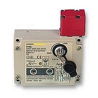
D4BL-1DRA-A
Specifications of D4BL-1DRA-A


Related parts for D4BL-1DRA-A


D4BL-1DRA-A Summary of contents
Page 1
... Without Indicator With Indicator 1NC /+1NO+1NC 1NC /+1NO+1NC (Slow action) (Slow action) D4BL-3CRA D4BL-3CRA-A D4BL-3CRB D4BL-3CRB-A D4BL-3CRC D4BL-3CRC-A D4BL-3CRG D4BL-3CRG-A D4BL Without Indicator With Indicator 2NC 2NC +1NC +1NC (Slow action) (Slow action) D4BL-3DRA D4BL-3DRA-A D4BL-3DRB D4BL-3DRB-A D4BL-3DRC D4BL-3DRC-A D4BL-3DRG D4BL-3DRG-A ...
Page 2
... PG13.5 2: G1/2 3: 1/2-14NPT 2. Built-in Switch C: 1NC/1NO (Slow-action) + 1NC (Slow-action) D: 2NC (Slow-action) + 1NC (Slow-action) 3. Head Mounting Direction R: Right Operation Key 1. Operation Key Type D4BL - K 1: Horizontal mounting 1 2: Vertical mounting 3: Adjustable mounting Specifications H RATINGS 1. IEC 947-5-1 and EN60947-5-1 AC-15 3A/250 V (6A/115 V for Display Models) 2 ...
Page 3
... C (14 to 131 F) with no icing 95% max. Pollution degree 3 (IEC947-5-1) Insulation class I (IEC536) 6P and 13 6P and 13 IP67 (60947-5-1) D4BL Motor load 2 1 0.2 A 0.1 A ...
Page 4
... VAC models +10% / (100% 110 VAC 10% (50/60 Hz) –15% Approx Lock monitor switch Key Ground terminal D4BL 230 VAC models 230 VAC 10% (50/60 Hz) Approx Operation key Lock plate Rotating drum Operation plunger Auxiliary plunger Rotating lever Safety switch Conduit opening (vertical wiring) ...
Page 5
... Recommended Circuit Connection Example 1. Connect the crimp-style terminals of each indicator unit to the internal terminals (terminals 31 and 12, 23 and 24, and 21 and 22) of the D4BL. 2. Each indicator unit must be connected in parallel with the contacts. When the contacts are open, the indicators will be LED lit ...
Page 6
... D4BL H OPERATING MODE (Example of Electromagnetic Interlock System Operating Mode of D4BL-jCjj) Operating I mode Door The protective door is open. Door switch Operation Key: The mechanical lock is released (contacts 31 and 32 are OFF). Main Switch: The normally closed contact is forcibly opened (contacts 11 and 12 are OFF). ...
Page 7
... D4BL Application Examples H CONNECTION EXAMPLE WITH OMRON’S G9S SAFETY RELAY UNIT G9S-301 (24 VDC)+D4BL-jCRG-j (Solenoid lock type)+D4D-j520 N Circuit Diagram PC output Closed Open PC output (Stop signal) ESSW S1: D4DN or D4BN Safety-door Lock Switch S2: D4BL Safety-door Lock Switch with solenoid lock S3: ...
Page 8
... G9S-321-Tj (24 VDC)+D4BL-jCRA-j/-jCRB-j (Mechanical lock type)+D4D-j520N Circuit Diagram PC output KM1 KM2 S3 Closed Open PC output (Stop signal) ESSW S1: Safety Switch (D4D-j520N) S2: D4BL Safety-door Lock Switch with mechanical lock KM1, KM2: Magnet Contactor (LC1-D) M: 3-phase motor ESSW: Emergency-stop switch (A22E) 8 Product Configuration Operation instruction A22E D4BL PC ...
Page 9
... Indicators D4BL-K2 15.6 (0.61) 7.3 (0.29) 15 (0.59) 26 (1.02) Two, R2.65 5.3 7.5 (0.30) 2.5 (0.10) 20 (0.79) 11.4 (0.45) 5.4 (0.21) D4BL 31 (1.22) 17 (0.67) 7 (0.27) 37.5 (1.48) Lock protection cap 86 (3.39) M4 cover Cover 16 (0.63) 39.6 (1.56) 46.3 (1.82) Conduit opening 53 ...
Page 10
... D4BL D4BL-K3 H WITH OPERATION KEY INSERTED D4BL + D4BL-K3 H INDICATOR UNIT Four terminal plates Two, 7 (0.28) dia. 7 (0.28) 16 (0.61) 26.8 53.2 (1.06) (2.10) 16 (0.61) 0.3 (0.01) 5.6 (0.22) 35 26.2 (1.38) (1.03) 61.2 (2.41 (1.02) 40 (1.57) 30 (1.18) 11.6 (0.47) 5.4 (0.21) 30 (1.18) 5.3 (0.21) dia. ...
Page 11
... AWB20 to AWG18 with seven conductors A UL2464-style cable is recommended. Apply sealing tape to the cable and conduit opening so that the D4BL can conform to IP67. Tighten the connector to a torque of 1.8 to 2.2 NSm (15.93 to 19.47 in lbs). Connect the Indicator Units to the D4BL after connecting the 7-con- ductor cable to the D4BL ...
Page 12
... NSm (7.08 to 8.85 in lbs) Four, M4 cover clamping screws 1.2 to 1.4 NSm (10.62 to 12.39 in lbs) Conduit Four, M5 Conduit opening cap 1.8 to 2.2 NSm Unit mounting screws 1.3 to 1.7 NSm (11.51 (15.93 to 19.47 in lbs) 4.9 to 5.9 NSm (43.37 to 11.51 in lbs) to 52.22 in lbs) D4BL Two, M5 Two, M5 ...
Page 13
... H OPERATION KEY The D4BL is provided with a shock absorptive damper when shipped attached to the D4BL in order to prevent the D4BL from be- ing damaged dropped accidentally. Be sure to remove the shock absorptive damper after the D4BL is mounted. Do not impose excessive force to the Operation Key in the switch or drop the Operation Key, or the Operation Key may be deformed or damaged ...
Page 14
... NOTE: DIMENSIONS SHOWN ARE IN MILLIMETERS. To convert millimeters to inches divide by 25.4. R OMRON ELECTRONICS, INC. One East Commerce Drive Schaumburg, IL 60173 1-800-55-OMRON Cat. No. CEDSAX3 10/99 Cover Crimp-style terminal Specifications subject to change without notice. D4BL OMRON CANADA, INC. 885 Milner Avenue Scarborough, Ontario M1B 5V8 416-286-6465 Printed in U.S.A. ...