D4NL-1AFA-B Omron, D4NL-1AFA-B Datasheet - Page 14
D4NL-1AFA-B
Manufacturer Part Number
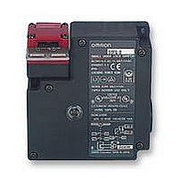
D4NL-1AFA-B
Description
SAFETY SWITCH
Manufacturer
Omron
Specifications of D4NL-1AFA-B
Contact Voltage Ac Max
240V
Contact Voltage Dc Max
24V
Contact Current Ac Max
10A
Contact Current Dc Max
200mA
Switch Terminals
Screw
Svhc
No SVHC (15-Dec-2010)
Approval Bodies
EN60747-5-1, IEC 947-5-1, EN1088,
Contact Configuration
SPST-NC / SPST-NO
Lead Free Status / Rohs Status
Lead free / RoHS Compliant


Refer to the “Precautions for All Switches” on page I-2 and “Precautions for All Safety Door Switches” on page A-2.
The Switch contacts can be used with either standard loads or
microloads. Once the contacts have been used to switch a load,
however, they cannot be used to switch smaller loads. The contact
surfaces will become rough once they have been used and contact
reliability for smaller loads may be reduced.
Change the head direction after changing the release
key to the UNLOCK position. Do not change the head
direction with the cover removed. Failure to observe
these points may result in Switch malfunction or damage.
Do not apply a force exceeding the specified holding force. Doing
so may break the Switch and the machine may continue to operate.
Either install another locking component (e.g., a stop) in addition to
the Switch, or use a warning sticker or an indicator showing the
lock status so that a force exceeding the specified holding force is
not applied.
Do not use the Switch submersed in oil or water or in locations
continuously subject to splashes of oil or water. Doing so may result
in oil or water entering the Switch. (The IP67 degree of protection of
the Switch specifies the amount of water penetration after the
Switch is submerged in water for a certain period of time.)
Although the Switch body is protected from the ingress of dust or
water, avoid the ingress of foreign substance through the key hole
on the head.
Otherwise, accelerated wear or breaking may result.
Always attach the cover after completing wiring and before using
the Switch. Electric shock may occur if the Switch is used without
the cover attached.
When switching general loads (250 VAC/3 A), do not operate two
circuits or more at the same time. Otherwise, insulation perfor-
mance may be degraded.
The release key is used to unlock the Switch in case of emergency
or if the power supply to the Switch stops.
If the release key setting is changed from LOCK to UNLOCK using
an appropriate tool, the lock will be released and the safety door
can be opened (mechanical lock models only).
After setting the release key to UNLOCK to, for example, change
the head direction or perform maintenance, be sure to return it to
LOCK setting before resuming operation.
If the release key is set to UNLOCK when the Switch is used for the
door of a machine room to ensure the safety of people performing
adjustment work inside, the door will not be locked when the door is
closed and no power will be supplied to the equipment.
Do not use the release key to start or stop machines.
The auxiliary lock must only be released by authorized personnel.
Do not impose a force exceeding 1 N·m on the release key screws.
The release key may be damaged and may not operated properly.
To prevent the release key from being used by unauthorized per-
sonnel, set it to LOCK and seal it with sealing wax.
OMRON SCIENTIFIC TECHNOLOGIES, INC.
USA
Tel. 1/888/510-4357
!
LOCK
UNLOCK
Canada
Tel. 1/866/986-6766
For the Latest Information
On the Internet: www.sti.com or www.omron.ca
If an attempt is made to open the door beyond the lock position when
the Switch is used for a hinged door at a location near to the hinged
side, where the Operation Key’s insertion radius is comparatively
small, the force imposed will be much larger than for locations far
from the hinged side, and the lock may be damaged.
The solenoid lock locks the door only when power is supplied to the
solenoid. Therefore, the door will be unlocked if the power supply to
the solenoid stops. Therefore, do not use solenoid lock models for
machines that may be operating and dangerous even after the
machine stops operating.
The life expectancy of the Switch will vary with the switching condi-
tions. Before applying the Switch, test it under actual operating con-
ditions and be sure to use it at a switching frequency that will not
lower its performance.
Be sure to tighten each screw of the Switch properly. Loose screws
may result in malfunction.
Three, M4
Terminal screw
Cover mounting screw
Head mounting screw
Operation Key mounting screw
Switch mounting screw
Connector
Cap screw
Mount the Switch and Operation Key securely to the applicable
tightening torque with M4 screws.
If the Switch is back-mounted, the release key can be operated
only from the bottom and the indicator cannot be used.
Use the designated OMRON Operation Key with the Switch. Using
another Operation Key may result in Switch damage.
Ensure that the alignment offset between the Operation Key and
the key hole does not exceed 1 mm.
Observe the specified insertion radius for the Operation Key and
insert it in a direction perpendicular to the key hole.
79
0.1
Guard Lock Safety-door Switch
32
55
0.1
0.1
D4DS-K1/-K2 (Horizontal/Vertical Mounting)
D4DS-K3 (Adjustable Mounting: Horizontal)
D4DS-K5 (Adjustable Mounting: Vertical)
0.59 to 0.78 N·m
0.49 to 0.69 N·m
0.49 to 0.59 N·m
2.35 to 2.75 N·m
0.49 to 0.69 N·m
1.77 to 2.16 N·m
1.27 to 1.67 N·m
15
41
0.1
0.1
40
or, 43
0.1
Two, M4
0.1
Two, M4
Two, M4
D4NL
AA-71
Related parts for D4NL-1AFA-B
Image
Part Number
Description
Manufacturer
Datasheet
Request
R

Part Number:
Description:
Safety Limit Switch
Manufacturer:
Omron
Datasheet:
Part Number:
Description:
Door Switch, 1NC/1NO Slo
Manufacturer:
Omron
Datasheet:
Part Number:
Description:
Limit Switch
Manufacturer:
Omron
Datasheet:
Part Number:
Description:
G1/2,1NC/1NO,1NC,1NO,Plst,lck
Manufacturer:
Omron
Datasheet:
Part Number:
Description:
Interlock Switch
Manufacturer:
Omron
Datasheet:
Part Number:
Description:
Limit Switch
Manufacturer:
Omron
Datasheet:
Part Number:
Description:
Locking Interlock Switch
Manufacturer:
Omron
Datasheet:
Part Number:
Description:
Interlock Door Switch
Manufacturer:
Omron
Datasheet:
Part Number:
Description:
Safety Door Switch
Manufacturer:
Omron
Datasheet:
Part Number:
Description:
Safety Door Switch
Manufacturer:
Omron
Datasheet:
Part Number:
Description:
Basic / Snap Action / Limit Switches 2NC+2NC SOL lock
Manufacturer:
Omron
Datasheet:
Part Number:
Description:
Basic / Snap Action / Limit Switches 3NC+1NC/1NO Metal head SOL.RLS
Manufacturer:
Omron
Datasheet:
Part Number:
Description:
SAFETY SWITCH
Manufacturer:
Omron
Datasheet:
Part Number:
Description:
SAFETY INTERLOCK SWITCH
Manufacturer:
Omron
Datasheet: