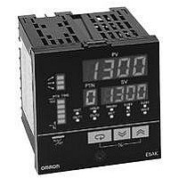
E5AK-TAA2500AC100/240 Omron, E5AK-TAA2500AC100/240 Datasheet - Page 19

E5AK-TAA2500AC100/240
Manufacturer Part Number
E5AK-TAA2500AC100/240
Description
Controllers, Process
Manufacturer
Omron
Datasheet
1.E53-AK01.pdf
(22 pages)
Specifications of E5AK-TAA2500AC100/240
Operating Temperature Max
55°C
Operating Temperature Min
-10°C
Temperature Accuracy ±
0.3%
Output Voltage Max
250VAC
Output Type
Relay
Thermocouple Type
J, K, T, E, L, U, N, R, S, B, W, PLII
Rohs Compliant
Yes
Lead Free Status / RoHS Status
Lead free / RoHS Compliant
Transfer Output
Connect transfer output (TRSF) to
terminal numbers 21 and 22. The
internal equalizing circuit for transfer
output is at right.
Precautions
J Operating Environment
•
•
•
•
J Mounting
•
•
•
J Connection
•
•
J Connection Example
•
•
•
Transfer output specifications are as follows:
4 to 20 mA,
Permissible load impedance: 600 Ω max.,
Resolution: Approx. 2600
Operate the Controller within the rated ambient operating
temperature, ambient operating humidity, and storage tem-
perature ranges.
Use the Controller according to the vibration resistance,
shock resistance, and enclosure ratings.
Do not install the Controller in places with corrosive gas or
excessive dust.
Do not install the Controller near machines generating high-
frequency noise.
The dimensions of the Controller conform to DIN 43700.
Recommended panel thickness is 1 to 8 mm.
Mount the Unit horizontally.
To reduce inductive noise influence, the lead wires connect-
ing the input type to the Controller must be separated from
the power lines and load lines.
Use the specified compensating conductors for thermocou-
ples. Use lead wires having a small resistance for platinum
resistance thermometers.
Wire the terminals of the Unit using solderless terminals.
The tightening torque applied to the terminal screws of the
Unit must be approximately 0.78 N S m or 8 kgf S cm.
Use the following type of solderless terminals for M3.5
screws.
7.2 mm max.
7.2 mm max.
4 to 20 mA
Ramp/Soak Process Controller
21
22
+
--
L
Communications
Terminal numbers 18 to 22 can be used only on controllers with
communications boards (E53-AK01/02/03). For details on wiring,
refer to Chapter 6, Using the Communications Function in the
E5AK-T/E5EK-T User Manuals (H088-E3-1 and H089-E3-1).
J Operation
•
•
•
•
•
•
•
The alarm outputs of a model with an alarm function may not
turn ON correctly when the model malfunctions. The use of
alarm equipment with the Controller is recommended.
The parameters and internal switch are set before shipping
so that the Unit will function normally. Change the settings of
the parameters and internal switch according to the
application if necessary.
After power has been supplied to the Controller, several se-
conds are required until the relay is turned ON. Consider this
time delay when designing sequenced circuits which
incorporate a Controller.
Do not use excessive force when removing the internal
mechanism from the housing. Protect the internal connector
or electronic parts of the Unit from shock.
Protect against static discharge when changing the settings
of the internal switch. Changing the settings on a grounded
conductive mat is recommended.
When connecting the control output board to the Tempera-
ture Controller or Process Controller, make sure that the
control output board is the appropriate type, or the system
may malfunction.
The heater burnout alarm will not be available if the linear
output board is used.
E5AK- -T/E5EK- -T
19


