E5CSVQ1T500AC100240V Omron, E5CSVQ1T500AC100240V Datasheet
E5CSVQ1T500AC100240V
Specifications of E5CSVQ1T500AC100240V


Related parts for E5CSVQ1T500AC100240V

E5CSVQ1T500AC100240V Summary of contents
Page 1
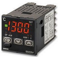
Temperature Controllers E5CSV Easy Setting Using DIP Switch and Simple Functions in DIN 48 × 48 mm-size Temperature Controllers • Easy setting using DIP and rotary switches. • Models with two alarms added to Series, ideal for temperature alarm applications. ...
Page 2
Ordering Information List of Models ■ Size Power supply Number of voltage alarm points 1/16 DIN 100 to 240 VAC 0 48 × 48 × × H × (See note.) 24 VAC/VDC 0 1 ...
Page 3
Characteristics ■ Setting accuracy Thermocouple (See note 1.): Platinum resistance thermometer (See note 2.): (±0.5% of indication value or ±1 ° C, whichever is greater) ±1 digit max. Indication accuracy (ambient temperature of 23 ° C) Influence of temperature R ...
Page 4
Temperature Range ■ Thermocouple Input Models Input Temperature 1,000 900 range 800 (selected 700 600 using switch) 500 400 300 200 (Default setting: 2) 200 100 Setting number Minimum setting unit Platinum Resistance Thermometer Input Models Input ...
Page 5
External Connection Diagram platinum resistance thermometer multi-input Note: 1. The voltage output (12 VDC, 21 mA) is not electrically isolated from the internal circuits. When using a grounding thermocouple, do not connect output terminals ground. Otherwise, ...
Page 6
Operation E5CSV Deviation indicators The indicator lights when the PV is greater than the SP and the indicator lights when the PV is less than the SP. The indicator (green) lights when the deviation is less than 1% FS (0.25% ...
Page 7
Sensor Type Specification Select the number on the temperature range switch to change the temperature range. Thermocouple (The default is 2.) Input K 1,000 900 800 700 600 SP 600 500 500 400 range 400 300 300 200 200 ...
Page 8
Operation Settings ON Use the control mode switches ( control mode. (All switches are OFF for the default settings Function selection 1 ON/OFF PID control ON PID ON/OFF control OFF Control 2 s ...
Page 9
Using the Control Mode Switches (1) Using ON/OFF Control and PID Control ON/OFF Control The control mode is set to ON/OFF control as the default setting Switch 1 OFF: ON/OFF control Control output ON ...
Page 10
Using the E5CSV in Devices for Fahrenheit-scale Users (Displaying in ° F) Turn ON switch 6 to display temperatures in ° Temperature Range for °F The temperature is set to ° F ...
Page 11
Protect Switch ON Protect Switch When the protect switch is ON, Up Key and Down Key operations are prohibited to prevent setting mistakes. Installation • All models in the E5CSV Series conform to DIN 43700 ...
Page 12
Error Displays and Causes In addition to the alarm indicator, errors notification is provided on the display. Be sure to remove the cause of the error promptly. Display status PV displayed as The process value is higher than the control ...
Page 13
Comparison with E5CS-X Model Number Legend ■ Previous model E5CS-@@@ Classification Symbol 1 Control output R Relay: SPDT (single-pole, double-throw) Q Voltage 2 Alarm output Blank No alarms 1 One alarm 3 Input type KJ Thermocouple (K, ...
Page 14
Terminal Arrangement ■ • The terminal arrangement has changed from a horizontal to vertical configuration. Previous model 100 to 240 VAC, 12 VDC, 50/ VAC/VDC 50/ 250 VAC (Resistive load) ...
Page 15
Dimensions Note: All units are in millimeters unless otherwise indicated. Controller ■ E5CSV 48×48 E5CSV + Adapter for Flush Mounting (Provided) Hard Protective Cover The Y92A-48B Protective Cover (hard type) is available for the following applications. • To protect the ...
Page 16
Precautions !CAUTION Do not touch the terminals while power is being supplied. Doing so may occasionally result in minor injury due to electric shock. Do not allow pieces of metal, wire clippings, or fine metallic shavings or filings from installation ...
Page 17
Use the product within the rated load and power supply. 10.Use a switch, relay, or other contact so that the power supply voltage reaches the rated voltage within 2 seconds. If the applied voltage is increased gradually, the power ...
Page 18
Temperature Controllers E5CSV ...
Page 19
E5CSV Temperature Controllers 19 ...
Page 20
... OR COMMERCIAL LOSS IN ANY WAY CONNECTED WITH THE PRODUCTS, WHETHER SUCH CLAIM IS BASED ON CONTRACT, WARRANTY, NEGLIGENCE, OR STRICT LIABILITY event shall the responsibility of OMRON for any act exceed the individual price of the product on which liability is asserted EVENT SHALL OMRON BE RESPONSIBLE FOR WARRANTY, REPAIR, OR OTHER CLAIMS REGARDING THE ...