FC5A-C16R2D IDEC, FC5A-C16R2D Datasheet - Page 2
FC5A-C16R2D
Manufacturer Part Number
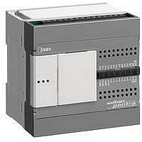
FC5A-C16R2D
Description
Programmable Logic Controller
Manufacturer
IDEC
Datasheet
1.FC5A-C16R2D.pdf
(2 pages)
Specifications of FC5A-C16R2D
No. Of Analog Outputs
7
Output Type
Relay
Supply Voltage Max
12VDC
No. Of Channels
16
Supply Voltage Min
10.2VDC
No. Of Analog Inputs
9
No. Of Digital Outputs
9
Lead Free Status / RoHS Status
Lead free / RoHS Compliant


Specifications con’t
Input Specifications
Relay Output Specifications
Input Internal Circuit
Part Number
Input Points
Rated Input Voltage
Input Voltage Range
Rated Input Current
Input Impedance
Turn ON Time
Turn OFF Time
Isolation
Input Type
External Load for I/O
Interconnection
Single Determination Method
Effect of Improper Input
Connection
Cable Length
Part Number
No. of Outputs
Output Points per
Common Line
Output Type
Maximum Load Current
Minimum Switching Load
Initial Contact Resistance
Electrical Life
Mechanical Life
Rated Load
Dielectric Strength
X0, X1
X2 to X15
Input
COM
Input
COM
IDEC Corporation
COM0
COM1
COM2
COM3
FC5A-C10R2D
1.8 kΩ
2.0 kΩ
240V AC/2A (resistive load, inductive load cos ø = 0.4)
FC5A-C10R2D FC5A-C16R2D FC5A-C24R2D
6 (6/1 common)
30V DC/2A (resistive load, inductive load L/R =7 ms)
Both sinking and sourcing input signals can be connected.
Between output terminal and internal circuit:
—
—
3m in compliance with electromagnetic immunity
If any input exceeding the rated value is applied,
4
3
1
Between output and
Between output terminals (COMs):
(rated load 1,800 operations/hour)
0.1 mA/0.1V DC (reference value)
(no load 18,000 operations/hour)
Between input terminals: Not isolated
20,000,000 operations minimum
Internal circuit: Photocoupler isolated
I6, I7, I10 to I15: 150 µs + filter value
permanent damage may be caused.
I6, I7, I10 to I15: 40 µs + filter value
100,000 operations minimum
•
12V DC sink/source input signal
1175 Elko Drive
I0 and I1: 16 µs + filter value
I2 to I5: 150 µs + filter value
I0 and I1: 2 µs + filter value
I2 to I5: 35 µs + filter value
1,500V AC, 1 minute
1,500V AC, 1 minute
1,500V AC, 1 minute
8A per common line
I2 to I7, I10 to I15: 2.0 kΩ
I2 to I7, I10 to I15: 6 mA
FC5A-C16R2D FC5A-C24R2D
30 mΩ maximum
9 (9/1 common)
Type 1 (IEC61131-2)
2A per point
I0 and I1: 1.8 kΩ
10.2 to 18V DC
I0 and I1: 6 mA
Not needed
1NO
—
7
4
2
1
Static
©2008 IDEC Corporation. All Rights Reserved. FC9Y-DS200-0 15K 07/08
terminals:
•
Sunnyvale, CA 94089
14 (14/1 common)
10
4
4
1
1
•
800-262-IDEC (4332)
Installation
When the CPU module is mounted in the standard upright position, all I/O
points can be turned on simultaneously at up to 55ºC operating temperature.
The CPU module can be installed facing upwards when the operating tempera-
ture is below 35ºC or sideways when the operating temperature is below 40ºC.
Mounting CPU Facing Up
Operating temperature below 35ºC
Dimensions
FC5A-C10R2D, FC5A-C16R2D
FC5A-C24R2D
Mounting Hole Layout
FC5A-C10R2D, FC5A-C16R2D
80.0
95.0
68.0
80.0
•
Fax: 408-745-5258
∗8.5 mm when the clamp is pulled out.
∗8.5 mm when the clamp is pulled out.
Mounting CPU Sideways
Operating temperature below 40ºC
•
www.IDEC.com/usa
FC5A-C24R2D
70.0
70.0
All dimensions in mm.
95.0
83.0
Related parts for FC5A-C16R2D
Image
Part Number
Description
Manufacturer
Datasheet
Request
R

Part Number:
Description:
Accessory, RS232C Communications Module for MicroSmart Pentra
Manufacturer:
IDEC Corporation

Part Number:
Description:
Programmable Logic Controller
Manufacturer:
IDEC
Datasheet:
Part Number:
Description:
INDICATOR INCANDESCENT LAMP, GREEN
Manufacturer:
IDEC
Datasheet:

Part Number:
Description:
LAMP, INDICATOR, INCAND, AMB
Manufacturer:
IDEC
Datasheet:
Part Number:
Description:
LAMP, INDICATOR, INCAND, GRN
Manufacturer:
IDEC
Datasheet:
Part Number:
Description:
LAMP, INDICATOR, INCAND, GRN
Manufacturer:
IDEC
Datasheet:
Part Number:
Description:
LAMP, INDICATOR, INCANDESCENT, RED
Manufacturer:
IDEC
Datasheet: