VCCF3 TELEMECANIQUE, VCCF3 Datasheet - Page 3
VCCF3
Manufacturer Part Number
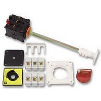
VCCF3
Description
LOAD BREAK SWITCH, 63A
Manufacturer
TELEMECANIQUE
Datasheet
1.XPEB110.pdf
(30 pages)
Specifications of VCCF3
No. Of Poles
3
Contact Voltage Ac Max
690V
Contact Current Ac Max
63A
Approval Bodies
UL, CSA, GL
Current Rating
63A
Depth Max
430mm
Depth Min
400mm
External Length / Height
83mm
External Width
60mm


10
1
2
3
4
5
6
7
8
9
9/2
λ
λ
λ
In practice, detected dangerous failure are dealt with by fault
reaction functions
s
dd
du
Functional Safety and Safety Integrity Level (SIL)
= rate of safe failures,
Residual risk
Residual risk
= rate of detected dangerous failures,
= rate of undetected dangerous failures
EN IEC 61511
EN IEC 61511
Safety integrity
Safety integrity
safety-related systems
safety-related systems
Practical risk covered
Practical risk covered
level
level
by other technology
by other technology
SIL
SIL
3
3
2
2
1
1
Risk reduction achieved by all safety-related systems and external risk reduction facilities
Risk reduction achieved by all safety-related systems and external risk reduction facilities
Process
Process
programmable electronic safety-related systems
programmable electronic safety-related systems
Functional safety of electrical / electronic /
Functional safety of electrical / electronic /
High demand or continuous
High demand or continuous
(Probability of a dangerous
(Probability of a dangerous
mode of operation
mode of operation
failure per hour)
failure per hour)
10
10
10
10
10
10
PFHD
PFHD
-8
-8
-7
-7
-6
-6
Tolerable risk
Tolerable risk
EN IEC 61508-3
EN IEC 61508-3
to < 10
to < 10
to < 10
to < 10
to < 10
to < 10
EN IEC 61508
EN IEC 61508
Software
Software
-7
-7
-6
-6
-5
-5
electronic / programmable electronic
electronic / programmable electronic
Practical risk covered by electrical /
Practical risk covered by electrical /
safety-related systems
safety-related systems
Safety of Systems and Equipment
Safety of Systems and Equipment
Risk reduction according to EN IEC 61508
b Safety
b Residual risk
b Protective measures
For machinery, the probability of dangerous failures per hour of a
control system is denoted in EN IEC 62061 as the PFHD
b
b
b
The rate of failures
The calculation of the PFHD for a system or subsystem depends on
several parameters:
different formula to calculate the PFHD. (see EN IEC 62061)
(The principal relationship is: PFHD = λ
be designed-out).
been taken.
contribute to risk reduction.
For each of the four different logical architectures A to D there is a
p
p
p
p
p
the dangerous failure rate (λ
the fault tolerance (e.g. redundancy) of the system
the diagnostic test interval (T2)
the proof test interval (T1) or lifetime whichever is smaller
the susceptibility to common cause failures (
is achieved by risk reduction (for those hazards that cannot
Actual risk reduction
Actual risk reduction
EN IEC 62061
EN IEC 62061
is the risk remaining after protective measures have
Necessary risk reduction
Necessary risk reduction
λ
can be expressed as follows:
λ = λ
realised by E/E/PE safety related systems
Machines
Machines
s
+ λ
Other versions: please consult your Schneider Electric agency.
d
Practical risk covered
Practical risk covered
dd
) of the subsystem elements
reduction facilities
reduction facilities
+λ
*Covering also the non-electrical technologies?e.g. hydraulics...
*Covering also the non-electrical technologies?e.g. hydraulics...
by external risk
by external risk
du
equipment under control risk
equipment under control risk
d
x 1h)
Safety related parts of
Safety related parts of
control systems
control systems
EN ISO 13849-1*
EN ISO 13849-1*
EN 954-1*
EN 954-1*
β
)
Increasing
Increasing
risk
risk
Related parts for VCCF3
Image
Part Number
Description
Manufacturer
Datasheet
Request
R

Part Number:
Description:
Control Contactor
Manufacturer:
TELEMECANIQUE
Datasheet:

Part Number:
Description:
Control Contactor
Manufacturer:
TELEMECANIQUE
Datasheet:

Part Number:
Description:
Contactor
Manufacturer:
TELEMECANIQUE
Datasheet:

Part Number:
Description:
Contactor
Manufacturer:
TELEMECANIQUE
Datasheet:
Part Number:
Description:
Control Contactor
Manufacturer:
TELEMECANIQUE
Datasheet:

Part Number:
Description:
CONTACTOR, 2NO/2NC, 9A, 230VAC
Manufacturer:
TELEMECANIQUE
Datasheet:

Part Number:
Description:
Contactor
Manufacturer:
TELEMECANIQUE
Datasheet:

Part Number:
Description:
CONTACTOR, 4KW, 400VAC
Manufacturer:
TELEMECANIQUE
Datasheet:

Part Number:
Description:
CONTACTOR, 5.5KW, 230VAC
Manufacturer:
TELEMECANIQUE
Datasheet:
Part Number:
Description:
CONTACTOR, 5.5KW, 400VAC
Manufacturer:
TELEMECANIQUE
Datasheet:

Part Number:
Description:
PILOT LIGHT HEAD, WHITE
Manufacturer:
TELEMECANIQUE
Datasheet:

Part Number:
Description:
LENS HEAD, BA 9S
Manufacturer:
TELEMECANIQUE
Datasheet:
Part Number:
Description:
LENS HEAD, BA 9S
Manufacturer:
TELEMECANIQUE
Datasheet:

Part Number:
Description:
LED BODY, 24V
Manufacturer:
TELEMECANIQUE
Datasheet:
Part Number:
Description:
LED BODY, 48V
Manufacturer:
TELEMECANIQUE
Datasheet: