589181000000018 AVX Corporation, 589181000000018 Datasheet - Page 22
589181000000018
Manufacturer Part Number
589181000000018
Description
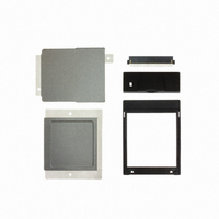
KIT COMPACT FLASH 50 POS
Manufacturer
AVX Corporation
Series
9181r
Datasheet
1.589181000000018.pdf
(24 pages)
Specifications of 589181000000018
Accessory Type
Compact Flash Kit
For Use With/related Products
Compact Flash - Type II
Lead Free Status / RoHS Status
Lead free / RoHS Compliant
Other names
478-4690
589181000000018
Q3289372
589181000000018
Q3289372


INSERTION FORCE AFTER THE THIRD
EXCHANGE OF A CONTACT
Due to the very low strain on the PCB hole an
exchange of pins in one hole is possible up to
3 times without a significant loss of retaining
force. Contacts can be exchanged at any posi-
tion within a press-in connection.
TRANSITION RESISTANCE
A significant advantage of the high push-out
force and the large contact area (contact length
min 1.4 mm or 2 mm for a 3.2 mm PCB) is the
very low transition resistance (≤ 0.2 mΩ) as well
as the vibration and corrosion free connection.
Given that the transition resistance between
male and female connectors in accordance
with DIN 41611 can be up to 20 mΩ, the
transition resistance of the press-in connection
can be virtually neglected.
AVX can guarantee a secure connection within
a frequency range of 10 - 2000 Hz at 20 G in
accordance with IEC 48 (sec) 334.
In the right hand picture we show
the contact length of the VARIPIN
into an 3.2 mm PC board. These
show a large connection surface
from section 1 to section 4 which
corresponds to a contact length of
more than 2 mm.
PRESS-FIT INSTALLATION METHODS
Right angle headers and receptacle connectors require a
press-in tool.
Vertical headers and receptacles do not require a special tool.
They are installed using the “Flat Rock” method. Flat Rock
20
Press-Fit Technology Overview
Section 1
Force
Section 2
Transition Resistance before and after SO
20
98
80
60
40
%
2
1
termination involves the use of a flat metal plate, slightly
larger than the length and width of the connector. Installed in a
press, the plate pushes down on the connector in a uniform
manner until the connector is properly seated.
100
80
90
70
50
40
30
20
10
[N]
60
●
●
●
●
●
●
1
2
3
1
2
3
0.1
●
1 = first push in, push out
2 = second push in, push out
3 = third push in, push out
Diagonal 1.24 mm
0.94
●
●
●
●
●
●
Section 3
●
0.2
●
●
Drilled hole
Metallized hole
Diagonal
VARIPIN
●
●
1.0
SO
Before SO
Push in force
Push out force
(mOhm)
2
Section 4
1.09 hole Ø (mm)
2
2
1.15 mm
1.0 mm
1.24mm
±0.03
Test
Section 5
Related parts for 589181000000018
Image
Part Number
Description
Manufacturer
Datasheet
Request
R

Part Number:
Description:
Manufacturer:
AVX Corporation
Datasheet:
Part Number:
Description:
Manufacturer:
AVX Corporation
Datasheet:
Part Number:
Description:
Manufacturer:
AVX Corporation
Datasheet:
Part Number:
Description:
Manufacturer:
AVX Corporation
Datasheet:
Part Number:
Description:
Manufacturer:
AVX Corporation
Datasheet: