C146 10E010 946 1 Amphenol-Tuchel Electronics, C146 10E010 946 1 Datasheet - Page 197
C146 10E010 946 1
Manufacturer Part Number
C146 10E010 946 1
Description
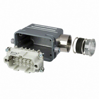
CONN 10POS CABLE SIDE POWER KIT
Manufacturer
Amphenol-Tuchel Electronics
Series
C146r
Specifications of C146 10E010 946 1
Style
Side Entry
Number Of Positions
10
Thread Size
PG21
Termination Style
Screw
Contents
Bushing, Hood, Male Insert
Connector Type
Rectangular Power
Gender
Plug
No. Of Contacts
10
No. Of Rows
2
Contact Gender
Pin
Connector Mounting
Cable
Contact Termination
Screw
Lead Free Status / RoHS Status
Lead free / RoHS Compliant
Size
-
Lead Free Status / RoHS Status
Lead free / RoHS Compliant, Lead free / RoHS Compliant
Other names
361-1159
C14610E0109461
C14610E0109461


Amphenol
C 146
Technische Informationen
Technical information
Stoßstrombelastbarkeit
Eine besondere Belastung kann sich für Steckverbinder und deren
Kontakte durch einen Stoßstrom ergeben, der z.B. durch einen Kurzschluss
in der Anlage oder durch Schaltvorgänge entstehen kann. Die kurzzeitig
sehr hohe Stromerwärmung kann nach außen nicht schnell genug
abgeführt werden, so dass es zu einer örtlich sehr starken Erwärmung der
Kontakte kommt, die z.B. in extremen Fällen zu einer Verschweissung
führen kann.
Durch unsere robuste Kontaktkonstruktion sind die hier beschriebenen
Steckverbinder gegenüber Stoßströmen relativ unempfindlich. Richtwerte
können dem nachfolgenden Diagramm 4 entnommen werden.
Diagramm 4
Stoßstrombelastbarkeit von Einzelkontakten
Kurve Nr.
1
2
3
4
Impulsdauer (S)
Impulse time (S)
Steckverbinder-Bauform
C146 E oder A mit Schraubkontakt
C146 E mit gestanztem Crimpkontakt
C146 S mit gestanztem Crimpkontakt
C146 D mit gestanztem Crimpkontakt
Impulse current carrying capacity
A surge can happen to a connector and its contacts by an impulse current,
e.g. through a short circuit in the system or by
switching operations. The short-timed high current heat cannot be
transferred outside fast enough so the contacts are stressed by the
high temperature which in the worst case can lead to a local weld.
The robust design of our connectors prevents most damage by impulse
currents.
The diagram 4 below can be used as a guideline.
Diagramm 4
Impulse current carrying capacity of single contacts
Curve No.
1
2
3
4
Connector style
C146 E or A with screw contact
C146 E with stamped crimp contact
C146 S with stamped crimp contact
C146 D with stamped crimp contact
197
Related parts for C146 10E010 946 1
Image
Part Number
Description
Manufacturer
Datasheet
Request
R

Part Number:
Description:
Heavy Duty Power Connectors PIN MODUL 10 WAY
Manufacturer:
Amphenol

Part Number:
Description:
Heavy Duty Power Connectors SOCKET MODULE 10 WAY
Manufacturer:
Amphenol

Part Number:
Description:
Heavy Duty Power Connectors PIN CONNECTOR 10 WAY
Manufacturer:
Amphenol

Part Number:
Description:
Heavy Duty Power Connectors FEMALE CONNECTOR 10 WAY
Manufacturer:
Amphenol

Part Number:
Description:
Male Receptacle 8+PE
Manufacturer:
Amphenol-Tuchel Electronics
Datasheet:

Part Number:
Description:
MEMORY CARD CONNECTOR, SMARTCARD
Manufacturer:
Amphenol-Tuchel Electronics
Datasheet:
Part Number:
Description:
Female Receptacle 8+PE
Manufacturer:
Amphenol-Tuchel Electronics
Part Number:
Description:
Male Cable Connector
Manufacturer:
Amphenol-Tuchel Electronics
Part Number:
Description:
Male Cable Connector
Manufacturer:
Amphenol-Tuchel Electronics
Part Number:
Description:
Specifications: Accessory Type: Cap (Cover) ; Color: Black ; Features: - ; For Use With/Related Products: Eco|mate
Manufacturer:
Amphenol-Tuchel Electronics