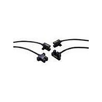
EE-SPX402-W2A Omron, EE-SPX402-W2A Datasheet - Page 5

EE-SPX402-W2A
Manufacturer Part Number
EE-SPX402-W2A
Description
PM 3.6mmSLOT PMS L-ON 1M CABLE
Manufacturer
Omron
Series
-r
Specifications of EE-SPX402-W2A
Sensing Distance
0.142" (3.6mm)
Sensing Method
Transmissive
Output Configuration
NPN - Open Collector/Light-ON
Mounting Type
Chassis Mount
Current - Supply
15mA
Voltage - Supply
5 V ~ 24 V
Package / Case
Module, Pre-Wired
Termination Style
Cable
Response Time
-
Lead Free Status / RoHS Status
Contains lead / RoHS compliant by exemption
Response Time
-
Lead Free Status / Rohs Status
Lead free / RoHS Compliant
Other names
EESPX402W2A
EE- -SPX302/402/304/404/305/405/306/406- -W2A
J EE-SPX306-W2A, EE-SPX406-W2A
Precautions
Refer to the Technical Information Section for general
precautions.
J WIRING
A cable with a thickness of 0.3 mm
of 2 m max. must be connected to the output terminals.
To use a cable longer than 2 m, attach a capacitor with a
capacitance of approximately 10 µF to the wires, as shown
below. The distance between the terminal and the capacitor must
be 2 m or less:
Avoid disconnecting from the photomicrosensor when power is
supplied to the photomicrosensor or the photomicrosensor could
be damaged.
If the metal mounting base is subjected to inductive electrical
noise, the photomicrosensor can be activated accidentally. If
noise is a problem, take the following precautions:
1. Connect the GND terminal to the mounting base, so there will
5
Cat. No. GC APMS-1
1-800-55-OMRON
OMRON ELECTRONICS LLC
One East Commerce Drive
Schaumburg, IL 60173
be no difference in electric potential between the photomicro-
sensor and mounting base.
OUT
NOTE: DIMENSIONS SHOWN ARE IN MILLIMETERS. To convert millimeters to inches divide by 25.4.
A capacitance of
10
2 m max.
5 to 24 VDC
µ
F min.
Optical axis
0 V
R
09/02
(0.29)
2
7.4
min. or AWG22 and a length
(0.14)
(0.26)
(0.28)
3.6
6.6
Extension
cable
7
Indicator
Indicator
OMRON ON- -LINE
Global -- http://www.omron.com
USA -- http://www.omron.com/oei
Canada -- http://www.omron.com/oci
(0.83)
(0.61)
21.2
15.6
Specifications subject to change without notice.
1.5 Max.
(0.24)
6
(0.12)
8±2
3
(0.54) 19
13.8
2. Connect the GND terminal to the mounting base via a
3. Insert a plastic insulating plate with a thickness of approxi-
Wire, as shown by the following illustration, to connect a small
inductive load (a relay for example) to the photomicrosensor. A
diode must be connected parallel to the relay to absorb the
reverse voltage.
J POWER SUPPLY
When using a standard switching regulator, ground the FG and G
terminal so that the photomicrosensor will be in a stable
operating condition.
1000±30
(0.75)
0.47-
mately 10 mm between the photomicrosensor and mounting
base.
2-3.5 dia. hole
(0.98)
25
EE- -SPX302/402/304/404/305/405/306/406- -W2A
µ
F capacitor.
OUT
Terminal Arrangement
IEC colors are shown in parentheses.
Red (Brown)
White (Black) OUTPUT
Black (Blue)
D
OMRON CANADA, INC.
Toronto, Ontario M1B 5V8
416-286-6465
885 Milner Avenue
Relay
GND (0 V)
V
CC
Switching
regulator
G
FG
5 to 24 VDC
0 V
Printed in U.S.A.


