SX100GD2 SENSYM, SX100GD2 Datasheet - Page 5
SX100GD2
Manufacturer Part Number
SX100GD2
Description
PRESSURE SENSOR, 0-100PSI
Manufacturer
SENSYM
Datasheet
1.SX30DN.pdf
(10 pages)
Specifications of SX100GD2
External Depth
11.94mm
External Length / Height
13.84mm
External Width
13.97mm
Hysteresis
0.5%
Lead Spacing
2.54mm
Linearity
0.2%
Operating Pressure Range
0 To 100psig
Operating Temperature Max
85°C


APPLICATION INFORMATION
General
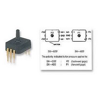
The SX family of pressure sensors functions
as a Wheatstone bridge. When pressure is
applied to the device (see Figure I) the
resistors in the arms of the bridge change
by an amount ∆.
The resulting differential output voltage V 0
is easily shown to be V O = V B x ∆. Since
the change in resistance is directly pro-
portional to pressure, V O can be written as:
Where: V O is the output voltage in mV
V OS is the offset error (the differential output
voltage when the applied pressure is zero).
The offset voltage presents little problem in
most applications, since it can easily be
corrected for in the amplifier circuitry, or
corrected digitally if a microprocessor is
used in the system.
Temperature effects
In this discussion, for simplicity of notation,
the change of a variable with temperature
will be designated with a dot (•) over the
variable. For example,
From equation (1), and ignoring the V OS
term, it in seen that for a given constant
pressure, the output voltage change, as a
function of temperature*, is:
Thus, in order for output voltage to be inde-
pendent of temperature, the voltage across
the bridge, V B , must change with tempera-
ture in the "opposite direction” from the
sensitivity change with temperature. From
the typical curves for the temperature
dependence of span (span = S x P x V B ),
July 2008 / 052
S
•
V O = S x P x V B ± V OS
Figure I. Button sensor bridge
=
S is the sensitivity in mV/V per psi
P is the pressure in psi
V B is the bridge voltage in volts.
change in sensitivity
change in temperature
•
V O = SPV B
•
schematic
(1)
=
(2)
δS
δT
it can be seen that the sensitivity change
with temperature is slightly non-linear and
can be correlated very well with an equation
of the form:
where T D is the temperature difference
between 25°C and the temperature of inte-
rest, S O is the sensitivity at 25°C, and beta
(ß) and rho (ρ) are correlation constants.
Fortunately, between 0°C and 70°C the
change in sensitivity with temperature is
quite linear, and excellent results can be
obtained over this temperature range by
ignoring the second-order temperature
dependent term. Operating outside the 0°C
and 70°C temperature range will require a
more rigorous mathematical approach and
the use of non-linear compensating cir-
cuitry, if accuracy of better than ±1 % is re-
quired. Because the majority of SX appli-
cations fall within the 0°C to 70°C operating
temperature range, the discussion and
circuit designs given here will ignore the
non-linear effects.
Thus:
Substituting equation (4) into equation (1)
and ignoring V OS , it can be shown that the
necessary bridge voltage, V B , will be of the
form:
V B =
where V BO is the bridge voltage at 25°C.
However, for the temperature range of
interest, and since ß is small (0.215%/°C
from the electrical tables), the above
expression can be approximated by:
with less than 1 % error. Thus to compen-
sate for a negative 2150 ppm/°C sensitivity
change with temperature, the bridge voltage
should increase with temperature at a rate
of +2150 ppm/°C.
The above value of bridge voltage change
will be used in the circuit discussions that
follow. That is to say, the required change
in terms of ppm/°C is:
The bridge input resistance*, R B also
changes with temperature and is quite linear
in the temperature range of interest. The
bridge resistance has a temperature
coefficient of typically:
( )
( )
S = S O [(1 - ßT D ) + ρT D 2 ]
S = S O (1 - ßT D )
This equation is again non-linear.
V B =V BO [1 +ßT D ]
R B
R B
V BO
(1-ßT D)
•
V B
V B
•
= V BO [(1 - ßT D + (ßT D )
= +2050 ppm/°C
= +750 ppm/°C
2
+...)]
(3)
(4)
This term enters into several compensation
circuit equations, particularly when the
bridge excitation is from a constant current
source.
To summarize, the following list indicates
how the sensor variables can be accommo-
dated
• Full-scale span from device to device.
• Temperature coefficient of span:
• Offset voltage:
• Offset voltage temperature coefficient:
Bridge compensation circuits
Although thermistors can be used to tempe-
rature compensate the bridge (and in fact
will be required for extended temperature
operation), they are inherently non-linear,
difficult to use in volume production, and
more expensive than the circuit approaches
shown here, which use inexpensive semi-
conductor devices The circuits shown have
been designed to incorporate a minimum
number of adjustments and allow inter-
changeability of devices with little variation
from device to device. In general, equations
for the bridge voltage and its change with
temperature are given to enable the user to
modify or adjust the circuitry as required.
1. Diode string (Figure II)
For systems using 6 V supplies, this method
of compensating for the effects of span over
temperature is the lowest cost solution The
diodes are small signal silicon diodes, such
as 1N914 or 1N4148, and do not have to
be matched.
www.sensortechnics.com
Make the gain adjustment in the op amp
circuitry
1) temperature compensate the bridge or
2) temperature compensate the op amp
Adjustment in op amp circuitry
Usually can be ignored. For more precise
design requirements, contact the factory
for information on how to compensate for
this term.
gain
Figure II. Diode String Span
Pressure sensors
Compensation
SX Series
5/10
Related parts for SX100GD2
Image
Part Number
Description
Manufacturer
Datasheet
Request
R

Part Number:
Description:
PRESSURE SENSOR, 0-1PSID
Manufacturer:
SENSYM
Datasheet:
Part Number:
Description:
PRESSURE SENSOR, 0-5PSID
Manufacturer:
SENSYM
Datasheet:
Part Number:
Description:
PRESSURE SENSOR, 0-100PSID
Manufacturer:
SENSYM
Datasheet:
Part Number:
Description:
PRESSURE SENSOR, 0-15PSIA
Manufacturer:
SENSYM
Datasheet:
Part Number:
Description:
PRESSURE SENSOR, 0-15PSID
Manufacturer:
SENSYM
Datasheet:
Part Number:
Description:
PRESSURE SENSOR, 0-30PSID
Manufacturer:
SENSYM
Datasheet:

Part Number:
Description:
PRESSURE SENSOR, 0-5" H2O
Manufacturer:
SENSYM
Datasheet:
Part Number:
Description:
PRESSURE SENSOR, 0-10" H2O
Manufacturer:
SENSYM
Datasheet:
Part Number:
Description:
PRESSURE SENSOR, 0-1PSID
Manufacturer:
SENSYM
Datasheet:

Part Number:
Description:
PRESSURE SENSOR, 0-1PSIG
Manufacturer:
SENSYM
Datasheet:
Part Number:
Description:
PRESSURE SENSOR, 0-100PSIG
Manufacturer:
SENSYM
Datasheet:

Part Number:
Description:
PRESSURE SENSOR, 0-15PSIA
Manufacturer:
SENSYM
Datasheet:
Part Number:
Description:
PRESSURE SENSOR, 0-15PSID
Manufacturer:
SENSYM
Datasheet:
Part Number:
Description:
PRESSURE SENSOR, 0-15PSIG
Manufacturer:
SENSYM
Datasheet:

Part Number:
Description:
Transducer
Manufacturer:
Honeywell / SenSym
Datasheet: