PKM13EPYH4000-A0 Murata, PKM13EPYH4000-A0 Datasheet - Page 9
PKM13EPYH4000-A0
Manufacturer Part Number
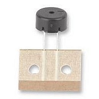
PKM13EPYH4000-A0
Description
SOUNDER, 4KHZ, 12.6MM
Manufacturer
Murata
Series
PKMr
Datasheet
1.PKM13EPYH4000-A0.pdf
(39 pages)
Specifications of PKM13EPYH4000-A0
Capacitance
5.5nF
External Depth
6.9mm
Sound Level Spl
70dB
Sound Level Distance
10cm
Svhc
No SVHC (18-Jun-2010)
Capacitance Max
7.15nF
Connector Type
PCB Pin
External Diameter
12.6mm
External Length /
RoHS Compliant
Technology
Piezoelectric
Sound Pressure Level
70 dB
Voltage Rating
30 V
Diameter
13 mm
Resonant Frequency
4 kHz
Lead Free Status / Rohs Status
Lead free / RoHS Compliant
Available stocks
Company
Part Number
Manufacturer
Quantity
Price

Part Number:
PKM13EPYH4000-A0
Manufacturer:
MURATA/村田
Quantity:
20 000


1
Please read CAUTION and Notice in this catalog for safety. This catalog has only typical specifications. Therefore you are requested
to approve our product specification or to transact the approval sheet for product specification, before your ordering.
1. Applying load on the center area of the diaphragm
2. Please consult with Murata or Murata
1. Please do not touch the component with bare hand
2. The component may be damaged if mechanical stress
3. Please pay attention to protect operating circuit from
4. If DC voltage is applied to the component, silver migration
5. The resistor should be used as shown in Fig. A.
6.Please pay enough attention not to pull lead wire too
8
Piezoelectric Diaphragms Notice
Notice (Soldering and Mounting)
may cause clack in the ceramic element. When the
diaphragm is supported by edge, the load should be
only applied around edge.
representative, in case of soldering on the
component.
Notice (Handling)
because electrode may be corroded.
over this specification is applied.
surge voltage provided by something of force such as
falling, shock and temperature changing.
may occur. Please pay full attention not to subject the
component to DC voltage for long periods.
A suitable resistance value should be chosen, preferably
1k to 2k . Instead of this measure, a diode may also be
applied as shown in Fig. B.
much because wire may be broken or soldering point may
come off.
IC
Fig.A
IC
Fig.B
R
P37E17.pdf 02.3.6
Related parts for PKM13EPYH4000-A0
Image
Part Number
Description
Manufacturer
Datasheet
Request
R

Part Number:
Description:
Murata Microblower 20x20 DCDC Driver Board - Samples Only
Manufacturer:
Murata
Part Number:
Description:
357-036-542-201 CARDEDGE 36POS DL .156 BLK LOPRO
Manufacturer:
Murata
Datasheet:
Part Number:
Description:
Manufacturer:
Murata
Datasheet:
Part Number:
Description:
Manufacturer:
Murata
Datasheet:
Part Number:
Description:
Manufacturer:
Murata
Datasheet:
Part Number:
Description:
Manufacturer:
Murata
Datasheet:
Part Number:
Description:
Manufacturer:
Murata
Datasheet:
Part Number:
Description:
Manufacturer:
Murata
Datasheet:
Part Number:
Description:
Manufacturer:
Murata
Datasheet:
Part Number:
Description:
BLM21BD751SN1On-Board Type (DC) EMI Suppression Filters
Manufacturer:
Murata
Datasheet:
Part Number:
Description:
BLM15AG100SN1On-Board Type (DC) EMI Suppression Filters
Manufacturer:
Murata
Datasheet:
Part Number:
Description:
NFE31PT222Z1E9On-Board Type (DC) EMI Suppression Filters
Manufacturer:
Murata
Datasheet:
Part Number:
Description:
Chip Coil
Manufacturer:
Murata
Datasheet:
Part Number:
Description:
Chip Coil
Manufacturer:
Murata
Datasheet: