UB500-30GM-E5-V15 PEPPERL & FUCHS, UB500-30GM-E5-V15 Datasheet - Page 2
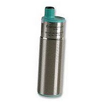
UB500-30GM-E5-V15
Manufacturer Part Number
UB500-30GM-E5-V15
Description
PROXIMITY SWITCH
Manufacturer
PEPPERL & FUCHS
Datasheet
1.UB500-30GM-E5-V15.pdf
(3 pages)
Specifications of UB500-30GM-E5-V15
Frequency Response Max
10Hz
Sensing Range Max
500mm
Sensor Input
Ultrasonic
Supply Voltage Dc Max
30V
Contact Current Max
200mA
External Length / Height
94mm
Ip/nema Rating
IP65
Operating Temperature Max
70°C
Operating Temperature Min
-25°C
Output Type
PNP
Response Time
480ms


Subject to reasonable modifications due to technical advances.
Pepperl+Fuchs Group • Tel.: Germany +49 621 776-0 • USA +1 330 4253555 • Singapore +65 67799091 • Internet http://www.pepperl-fuchs.com
Hinweise
Notes
Description of the sensor functions
Synchronisation
The sensor features a synchronisation input for the suppression of mutual interfer-
ence. If this input is not used, the sensor will operate using an internally generated
clock rate. The synchronisation of multiple sensors can be realised as follows:
External synchronisation:
The sensor can be synchronised by the external application of a square wave volt-
age. A synchronisation pulse at the synchronisation input starts a measuring cycle.
The pulse must have a duration greater than 100 µs. The measuring cycle starts
with the falling edge of a synchronisation pulse. Two operating modes are available:
1. Multiple sensors can be controlled by the same synchronisation signal. The sensors are synchro-
2. The synchronisation pulses are sent cyclically to individual sensors. The sensors operate in mul-
Internal synchronisation:
The synchronisation connections of up to 5 sensors capable of internal synchroni-
sation are connected to one another. When power is applied, these sensors will op-
erate in multiplex mode.
The state of the switch output will not change until the switching threshold has been
exceeded five times as an average of the five measurements is determined inter-
nally. A low level > 1 s or an open synchronisation input will result in the normal op-
eration of the sensor.
Synchronisation cannot be performed during TEACH-IN and vice versa. The sen-
sors must be operated in an unsynchronised manner to teach the switching point.
A high level at the synchronisation input disables the sensor.
Note:
If the option for synchronization is not used, the synchronization input has to be con-
nected to ground (0V) or the sensor has to be operated via a V1 cable connector
(4-pin).
Adjusting the switching points
The ultrasonic sensor features an analogue output with two teachable evaluation
limits. These are set by applying the supply voltage -U
input. The supply voltage must be applied to the TEACH-IN input for at least 1 s.
LEDs indicate whether the sensor has recognised the target during the TEACH-IN
procedure. Evaluation limit A1 is taught with -U
the switching point and the output functions the programming unit UB-PROG2 can
be used.
Five different output functions can be set:
1. Window mode, normally-open function
2. Window mode, normally-closed function
3. One switching point, normally-open function
4. One switching point, normally-closed function
5. Detection of object presence
TEACH-IN window mode, normally-open function
- Set target to near switching point
- TEACH-IN switching point A1 with -U
- Set target to far switching point
- TEACH-IN switching point A2 with +U
TEACH-IN window mode, normally-closed function
- Set target to near switching point
- TEACH-IN switching point A2 with +U
- Set target to far switching point
- TEACH-IN switching point A1 with -U
TEACH-IN one switching point, normally-open function
- Set target to near switching point
- TEACH-IN switching point A2 with +U
- Cover sensor with hand or remove all objects from sensing range
- TEACH-IN switching point A1 with -U
TEACH-IN one switching point, normally-closed function
- Set target to near switching point
- TEACH-IN switching point A1 with -U
nised.
tiplex mode.
B
B
B
B
B
B
B
B
, A2 with +U
B
or +U
B
B
. For simple setting
to the TEACH-IN
Bestellbezeichnung
Model number
UB500-30GM-E5-V15
Accessories
Copyright Pepperl+Fuchs, Printed in Germany
Characteristic curves/additional
information
Programmed switching output function
Mounting aid
BF30
BF30F
BF5-30
M-105
Sound deflectors
UVW90-M30
UVW90-K30
Programming Unit
UB-PROG2
Cable sockets
V15-G-2M-PVC
V15-W-2M-PUR
*)
tion „Accessories“.
1. Window mode, normally open function
A1 < A2:
2. Window mode, normally closed function
A2 < A1:
3. One switch point, normally open function
A1 -> ∞:
4. One switch point, normally closed function
A2 -> ∞:
5. A1 -> ∞, A2 -> ∞: Detection of object presence
Characteristic response curve
0.0
0.2
0.4
Object detected: Switch output closed
No object detected: Switch output open
For additional cable sockets see sec-
90 80
Curve 1: flat surface 100 mm x 100 mm
Curve 2: round bar, Ø 25 mm
Distance [m]
70
60
A1
A1
A2
A2
50
*)
0.6
2
40
A2
A1
0.8
30
object range
Angle [degree]
1
1.0
-20
20
-10
10
0
2
Related parts for UB500-30GM-E5-V15
Image
Part Number
Description
Manufacturer
Datasheet
Request
R

Part Number:
Description:
WE77/EX-1 230V, PEPPERL + FUCHS, SWITCH ISOLATOR 230V
Manufacturer:
PEPPERL & FUCHS
Datasheet:
Part Number:
Description:
Rotary Encoders - Absolute
Manufacturer:
PEPPERL & FUCHS


Part Number:
Description:
LED Pilot Light
Manufacturer:
PEPPERL & FUCHS
Datasheet:

Part Number:
Description:
LED Pilot Light
Manufacturer:
PEPPERL & FUCHS
Datasheet:
Part Number:
Description:
LED Pilot Light
Manufacturer:
PEPPERL & FUCHS
Datasheet:
Part Number:
Description:
LED Pilot Light
Manufacturer:
PEPPERL & FUCHS
Datasheet: