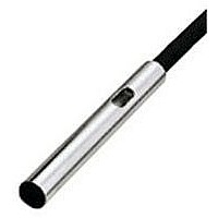
GX-3SB PANASONIC EW, GX-3SB Datasheet - Page 9

GX-3SB
Manufacturer Part Number
GX-3SB
Description
Inductive Proximity Sensor
Manufacturer
PANASONIC EW
Datasheet
1.GX-3SB.pdf
(10 pages)
Specifications of GX-3SB
Sensor Input
Inductive
Sensing Range
0.8mm
Supply Voltage Range Dc
12V To 24V
Lead Free Status / RoHS Status
Lead free / RoHS Compliant
PRECAUTIONS FOR PROPER USE
Distance from surrounding metal
Mutual interference
GX
Embedding of the sensor in metal
Face to face mounting
Parallel mounting
As metal around the sensor may affect the sensing
performance, pay attention to the following points.
Influence of surrounding metal
The surrounding metal will affect the sensing
performance. Keep the minimum distance specified in the
table below.
Sensing range may decrease if the sensor is completely
embedded in metal. Especially for the non-threaded type
and the non-shielded type, keep the minimum distance
specified in the table below.
When two or more sensors are installed in parallel or face
to face, keep the minimum separation distance specified
below to avoid mutual interference.
752
G
J
E
F
H
Metal
Model No.
Model No.
GX-3S
GX-4S
GX-5S
GX-8ML
GX-3S
GX-4S
GX-5S
GX-5M
GX-8M
GX-8ML
Model No.
GX-3S
GX-4S
GX-5S
GX-5M
GX-8M
GX-8ML
F (mm in) G (mm in)
H (mm in) J (mm in)
10
16
16
20
10
20
50
3
3
5
0.118
0.118
0.197
0.394
0.630
0.630
0.787
0.394
0.787
1.969
E (mm in)
4
4
8
3
3
3
"12
"12
"15.4
"30
16
16
15
10
15
30
0.118
0.118
0.157
0.118
0.157
0.315
0.630
0.630
0.591
0.394
0.591
1.181
"0.472
"0.472
"1.181
"0.606
Sensing range
Correction coefficient
Note: The sensing range also changes if the sensing object is plated.
Others
Metal
Iron
Stainless steel
(SUS304)
Brass
Aluminum
The sensing range is specified for the standard sensing
object. With a non-ferrous metal, the sensing range is
obtained by multiplying with the correction coefficient
specified below.
Do not use during the initial transient time (10 ms) after
the power supply is switched on.
When the sensor is mounted on a moving base, stress
should not be applied to the sensor cable joint.
GX-3S , GX-4S
short-circuit protection at the output. Do not connect them
directly to a power supply or a capacitive load.
Sensors attached with flexible cable are also available.
They are identified by the suffix ‘-R’ at the end of the
model No.
Model No.
Stress
0.65 approx.
0.36 approx.
0.30 approx.
GX-3S
GX-4S
1
and GX-5M
Refer to
p.1152l
0.83 approx.
0.61 approx.
0.58 approx.
GX-5M
1
do not incorporate a
for general precautions.
Stress
0.70 approx.
0.40 approx.
0.35 approx.
GX-5S
GX-8M
GX-8ML
1


