E2EC-X4D1 Omron, E2EC-X4D1 Datasheet - Page 6
E2EC-X4D1
Manufacturer Part Number
E2EC-X4D1
Description
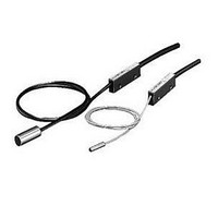
Inductive Proximity Sensor
Manufacturer
Omron
Series
E2ECr
Specifications of E2EC-X4D1
Sensor Input
Inductive
Sensing Range
4mm
Supply Voltage Range Dc
10V To 30V
Supply Voltage Max
30VDC
Sensing Range Max
4mm
Mounting Type
Panel
Switch Terminals
Cable
Output Type
NO
Maximum Operating Temperature
+ 70 C
Supply Voltage
24 V
Operating Supply Voltage
10 V to 30 V
Sensing Distance
4 mm
Minimum Operating Temperature
- 25 C
Maximum Output Current
100 mA
Features
NO
Sensor Type
Inductive
Sensing Object
Metallic
Response Frequency
1kHz
Material - Body
Brass
Shielding
Shielded
Voltage - Supply
10 V ~ 30 V
Terminal Type
2-Wire
Package / Case
Cylinder, Threaded - M12
Lead Free Status / RoHS Status
Lead free / RoHS Compliant


Safety Precautions
Refer to Warranty and Limitations of Liability.
This product is not designed or rated for ensuring
safety of persons either directly or indirectly.
Do not use it for such purposes.
Do not use this product under ambient conditions that exceed the
ratings.
● Design
Influence of Surrounding Metal
When mounting the Sensor within a metal panel, ensure that the
clearances given in the following table are maintained. Failure to
maintain these distances may cause deterioration in the performance
of the Sensor.
Influence of Surrounding Metal
Influence of Temperature
Incorrect operation may occur if there is a large temperature
difference between the Sensor Head and the Amplifier Unit.
Amplifier Mounting Bracket for DC 2-Wire Models
Mounting
1. Insert the Amplifier into the trapezoidal end (i.e., the fixing side) of
2. Press the other end of the Amplifier onto the Bracket.
Model
E2EC-CR8D@
E2EC-C1R5D@
E2EC-C3D@
E2EC-X4D@
E2EC-CR5C1
E2EC-C2R5C1
the Mounting Bracket.
l
Precautions for Correct Use
m
Item
1
0
l
Mounting Bracket
WARNING
Amplifier
3
5.4
8
12
3
8
d
D
d dia.
(Unit: mm)
D
0
Cable
2
2.4
4.5
9
12
1.5
10
m
l
m
6
10.8
16
24
5
21
n
n
Mutual Interference
When installing Sensors face-to-face or side-by-side, ensure that the
minimum distances given in the following table are maintained.
Mutual Interference
Note: Values in parentheses apply to Sensors operating at different frequencies.
● Mounting
Permissible Tightening Range and Torque
Dismounting
1. Lightly press the hook on the Mounting Bracket with a flat-blade
2. The Amplifier will be automatically released due to the spring force
Model
E2EC-CR8D@
E2EC-C1R5D@
E2EC-C3D@
E2EC-X4D@
E2EC-CR5C1
E2EC-C2R5C1
• Refer to the following table for the
E2EC-CR8D@
E2EC-C1R5D@
E2EC-C3D@
E2EC-CR5C1
E2EC-C2R5C1
• The tightening torque applied to the E2EC-
torque and tightening ranges
applied to mount the E2EC-C
Unthreaded Cylindrical Model.
Tightening must be as given in
the following table.
X4D@ Threaded Cylindrical Models must be
12 N·m max.
screwdriver.
of the Mounting Bracket.
Model
Item
A
30 (15)
40 (20)
20 (10)
40 (20)
18 (4)
15 (8)
A
Tightening
6 to 10 mm
8 to 16 mm
6 to 16 mm
8 to 16 mm
screwdriver
Flat-blade
(Unit: mm)
10.8 (5.4)
24 (12)
25 (15)
16 (8)
15 (3)
6 (3)
B
2
B
Set screw tightening
1
0.49 N·m
0.98 N·m
0.39 N·m
A
E2EC
Dimpled
end of set
screw (M3)
6
Related parts for E2EC-X4D1
Image
Part Number
Description
Manufacturer
Datasheet
Request
R

Part Number:
Description:
Proximity Sensors E2EC-C3D1 W/ M12 PIG TAIL SPECL
Manufacturer:
Omron
Datasheet:
Part Number:
Description:
Proximity Sensors PROX E2EC-C3D1 w/ M1 2 Connect.
Manufacturer:
Omron
Datasheet:
Part Number:
Description:
PROX,3mm PNP-NC In Line Amp
Manufacturer:
Omron
Datasheet:

Part Number:
Description:
Proximity Sensors PROX 3mm In-line Amp NPN-NC
Manufacturer:
Omron
Datasheet:
Part Number:
Description:
Proximity Sensors 3mm .5mm SENS NPN
Manufacturer:
Omron
Datasheet:
Part Number:
Description:
Proximity Sensors INDUCTIVE N.O. PNP
Manufacturer:
Omron
Datasheet:

Part Number:
Description:
Inductive Proximity Sensor
Manufacturer:
Omron
Datasheet:
Part Number:
Description:
PROX 3mm In-line Amp DC2W-NC
Manufacturer:
Omron
Datasheet:
Part Number:
Description:
PROX 8mm In-line Amp PNP-NO
Manufacturer:
Omron
Datasheet:

Part Number:
Description:
PROXIMITY SENSOR
Manufacturer:
Omron
Datasheet: