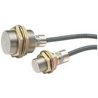
E2E-X10F1 Omron, E2E-X10F1 Datasheet - Page 31

E2E-X10F1
Manufacturer Part Number
E2E-X10F1
Description
Inductive Proximity Sensor
Manufacturer
Omron
Series
E2Er
Specifications of E2E-X10F1
Sensor Input
Inductive
Sensing Range
10mm
Supply Voltage Range Dc
10V To 40V
Sensor Housing
Barrel
Supply Voltage Max
30VDC
Sensing Range Max
10mm
Switch Terminals
Cable
Supply Voltage Min
10VDC
Maximum Operating Temperature
+ 85 C
Operating Supply Voltage
10 V to 40 V
Sensing Distance
10 mm
Minimum Operating Temperature
- 40 C
Features
NO
Sensor Type
Inductive
Sensing Object
Metallic
Response Frequency
3kHz
Material - Body
Nickel-Plated Brass
Shielding
Shielded
Voltage - Supply
10 V ~ 30 V
Output Type
PNP-NO
Terminal Type
3-Wire
Package / Case
Cylinder, Threaded - M30
Sensor Output
PNP
Rohs Compliant
Yes
Lead Free Status / RoHS Status
Lead free / RoHS Compliant
Available stocks
Company
Part Number
Manufacturer
Quantity
Price
Company:
Part Number:
E2E-X10F1-Z
Manufacturer:
AZBIL
Quantity:
1 000
E2E-CR8C@/CR8B@/X1C@/X1B@-M5 DC 3-wire Models
E2E-X@Y@-M1 AC 2-wire Models
Precautions
Mounting
Do not tighten the nut with excessive force. A washer must be used
with the nut.
Note: The table below shows the tightening torques for part A and
NO
NC
M5
M8
M12
M18
M30
M8-3pin
Connector
Operation mode
Shielded
Unshielded
part B nuts. In the previous examples, the nut is on the sensor
head side (part B) and hence the tightening torque for part B
applies. If this nut is in part A, the tightening torque for part A
applies instead.
Model
Shielded Model
NO/NC
NO/NC
Part B Part A
Operation mode
1 N·m
9 mm
3 mm
30 N·m
70 N·m
180 N·m
Length
E2E-X@Y1-M1
E2E-X@Y2-M1
Part A
Unshielded Model
9 N·m
Applicable models
Torque
E2E-CR8B@-M5
E2E-CR8C@-M5
E2E-X1C@-M5
E2E-X1B@-M5
Applicable models
Part B Part A
12 N·m
Torque
Part B
Note: Terminals 1 and 2 are not used.
Note: Terminals 3 and 4 are not used.
E2E/E2E2
Refer to the following to mount the E2E-CR6, -CR8 and E2E-C1
non-screw models.
Tighten the screw to a torque of 0.2 N·m maximum to secure the
E2E-CR6, -CR8 and a torque of 0.4 N·m maximum to secure the
E2E-C1.
Load
Load
E2E-CR6:
E2E-CR8, -C1: 8 to 21 mm
1
1
4
4
Cylindrical Proximity Sensor
Pin arrangement
Pin arrangement
3
3
Load
Load
9 to 21 mm
M3 hole
No screw is provided
with the E2E-CR6,
-CR8 or E2E-C1.
DC
DC
Load
Load
31


