SDX15G2 SENSYM, SDX15G2 Datasheet - Page 2
SDX15G2
Manufacturer Part Number
SDX15G2
Description
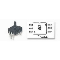
PRESSURE SENSOR, 0-15PSIG
Manufacturer
SENSYM
Datasheet
1.SDX01D4.pdf
(4 pages)
Specifications of SDX15G2
External Depth
11.94mm
External Length / Height
15.1mm
External Width
13.97mm
Hysteresis
1%
Linearity
0.2%
Operating Pressure Range
0 To 15psig
Operating Temperature Max
85°C


PRESSURE SENSOR CHARACTERISTICS (all devices)
Maximum ratings
Supply voltage V
Maxium pressure on any port
Lead temperature (soldering 4 sec.)
STANDARD PRESSURE RANGES
* Maximum pressure above which causes permanent sensor failure.
COMMON PERFORMANCE CHARACTERISTICS
June 2008 / 062
Specification notes:
10.
11.
Part number
SDX01...
SDX05...
SDX15A...
SDX15G2, ...D4
SDX30A...
SDX30G2, ...D4
SDX100A...
SDX100G2, ...D4
Characteristic
Zero pressure offset
Combined linearity and hysteresis
Temperature effect on span (0 to 50°C)
Temperature effect on offset (0 to 50°C)
Repeatability
Input impedance
Output impedance
Common-mode voltage
Response time
Long term stability of offset and span
1.
2.
3.
4.
5.
6.
7.
8.
9.
Reference conditions: supply voltage, V
For absolute devices only, pressure is applied to port 1 and the output polarity is reversed.
Span is the algebraic difference between the output voltage at full-scale pressure and the output at zero pressure. Span is
ratiometric to the supply voltage.
See Definition of Terms. Hysteresis - the maximum output difference at any point within the operating pressure range for
increasing and decreasing pressure.
Maximum error band of the offset voltage and the error band of the span, relative to the 25°C reading.
Maximum difference in output at any pressure with the operating pressure range and temperature within 0 to +50°C after:
Input impedance is the impedance between pins 2 and 5.
Output impedance is the impedance between pins 1 and 3.
This is the common-mode voltage of the output arms (pins 1 and 3) for V
Response time for a 0 psi to full-scale span pressure step change, 10 to 90 % rise time.
Long term stability over a one year period.
Maximum pressure at any port is the maximum operating plus common-mode pressure which can be applied. The proof
pressure for the forward gage of all devices in the D4-package is the specified value or 100 psi, whatever is less.
5
S
9
6
7
8
Low cost compensated pressure sensors in DIP package
Operating pressure
a) 100 temperature cycles, 0 to + 50°C
b) 1.0 million pressure cycles, 0 psi to full-scale span
3
0 - 100 psig/d
10
0 - 15 psig/d
0 - 30 psig/d
0 - 100 psia
0 - 1 psig/d
0 - 5 psig/d
0 - 15 psia
0 - 30 psia
4
4
S
= 12 V
150 psig
+20 V
250°C
DC
DC
, T
A
= 25°C, common-mode line pressure = 0 psig, pressure applied to port 2.
Proof pressure
Environmental specifications
Temperature ranges
Humidity limits
150 psi
150 psi
30 psi
30 psi
60 psi
60 psi
20 psi
20 psi
Min.
-1.0
1.3
---
---
---
---
---
---
---
---
1
Compensated
Operating
Storage
S
= 12 V
11
DC
.
Typ.
±0.2
±0.4
±0.2
±0.2
±0.1
100
4.0
4.0
3.0
0
17.37 mV
86.85 mV
86.85 mV
86.85 mV
86.85 mV
57.9 mV
96.5 mV
96.5 mV
www.sensortechnics.com
Min.
Full-scale span
Max.
+1.0
±1.0
±2.0
±1.0
±0.5
SDX Series
5.0
100 mV
100 mV
---
---
---
---
18 mV
60 mV
90 mV
90 mV
90 mV
90 mV
Typ.
-55 to +125°C
0 to 100% RH
1,2
-40 to +85°C
18.63 mV
93.15 mV
93.15 mV
93.15 mV
93.15 mV
103.5 mV
103.5 mV
62.1 mV
%FSO
%FSO
%FSO
Unit
µsec
Max.
mV
mV
V
mV
kΩ
kΩ
0 to 50°C
DC
2/4
Related parts for SDX15G2
Image
Part Number
Description
Manufacturer
Datasheet
Request
R

Part Number:
Description:
PRESSURE SENSOR, 0-1PSID
Manufacturer:
SENSYM
Datasheet:
Part Number:
Description:
PRESSURE SENSOR, 0-5PSID
Manufacturer:
SENSYM
Datasheet:
Part Number:
Description:
PRESSURE SENSOR, 0-100PSID
Manufacturer:
SENSYM
Datasheet:
Part Number:
Description:
PRESSURE SENSOR, 0-15PSIA
Manufacturer:
SENSYM
Datasheet:
Part Number:
Description:
PRESSURE SENSOR, 0-15PSID
Manufacturer:
SENSYM
Datasheet:
Part Number:
Description:
PRESSURE SENSOR, 0-30PSID
Manufacturer:
SENSYM
Datasheet:

Part Number:
Description:
PRESSURE SENSOR, 0-5" H2O
Manufacturer:
SENSYM
Datasheet:
Part Number:
Description:
PRESSURE SENSOR, 0-10" H2O
Manufacturer:
SENSYM
Datasheet:
Part Number:
Description:
PRESSURE SENSOR, 0-1PSID
Manufacturer:
SENSYM
Datasheet:

Part Number:
Description:
PRESSURE SENSOR, 0-1PSIG
Manufacturer:
SENSYM
Datasheet:
Part Number:
Description:
PRESSURE SENSOR, 0-100PSIG
Manufacturer:
SENSYM
Datasheet:

Part Number:
Description:
PRESSURE SENSOR, 0-15PSIA
Manufacturer:
SENSYM
Datasheet:
Part Number:
Description:
PRESSURE SENSOR, 0-15PSID
Manufacturer:
SENSYM
Datasheet:

Part Number:
Description:
PRESSURE SENSOR, 0-100PSI
Manufacturer:
SENSYM
Datasheet:

Part Number:
Description:
Transducer
Manufacturer:
Honeywell / SenSym
Datasheet: