SCX01DN SENSYM, SCX01DN Datasheet - Page 5
SCX01DN
Manufacturer Part Number
SCX01DN
Description
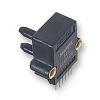
PRESSURE SENSOR, 0-1PSID
Manufacturer
SENSYM
Datasheet
1.SCX01DN.pdf
(10 pages)
Specifications of SCX01DN
External Depth
26.2mm
External Length / Height
25.4mm
External Width
27.9mm
Fixing Centres
21.6mm
Hysteresis
1%
Lead Spacing
2.54mm
Linearity
1%
Operating Pressure Range
0 To 1psid
Available stocks
Company
Part Number
Manufacturer
Quantity
Price

Company:
Part Number:
SCX01DNC
Manufacturer:
SIPEX
Quantity:
101


APPLICATION INFORMATION
Parallel A/D conversion
The SCX sensor can be easily interfaced to a microprocessor bus.
Using an A/D converter, for a 0 to 1 psig input, the circuit in Figure
C will provide an eight-bit parallel output which is proportional to
applied pressure. The circuit allows for easy calibration and uses a
single 5 V supply.
Circuit description
The output signal of the sensor is amplified by A
in resistor R
shown in the following gain equation:
By adjusting R
initial offset voltage. A zener diode (LT1004) sets the initial input
voltage and provides the reference voltage for the converter. The
converter will output the maximum digital code when the A/D
converter´s input voltage, V
1
where the binary output is updated continously*. The only
requirement is that the WR and INTR must be momentarily grounded
after power-up to ensure proper operation.
Adjustment procedure
1. With no pressure applied, adjust the offset pot R
2. Apply full-scale pressure (1 psig) to port B, and adjust the full-
3. Repeat procedure if necessary.
* For timing specifications and bus interface, see the ADC0804
August 2005 / 053
/
2
Datasheet from National Semiconductor.
LSB. The A/D converter, as shown, is a free-running configuration
are zero except the LSB, which should be switching between
one and zero.
scale pot R
be flickering between one and zero.
1
, can be adjusted to calibrate the gain of the circuit as
3
2
, V
V
until all bits are ones except the LSB which should
OUT
IN
Figure A. Low pressure circuits provide a 2 to 5 V output for a 0-10 in. W.C. pressure input
(-) on the A/D converter is used to adjust the
= V
IN
OUT
2 [1+
, is twice the zener voltage, minus 1
R
/
R1
]
1
(cont.)
, and A
3
until all bits
2
. The pot,
Precision compensated pressure sensors
Serial A/D conversion
The circuit shown in Figure D is similar to that shown in Figure C,
except the output is bit serial. Also shown (under the dashed line)
is a complimentary circuit for converting the serial output to a par-
allel output for simplified testing.
Circuit description
The three op amp configuration allows V
common-mode voltage as V
CMRR of the ADC0831. R
such that
The A/D converter will output the maximum digital code when V
is equal to the zener voltage minus 1
circuit can be nulled out by adjusting pot R
requires only a clock and a chip select (CS) line in order to operate.
As shown in Figure E, when CS goes low, the A/D converter will
start a new conversion on the next rising edge of the clock. On the
next falling edge of the clock, D
starting with the MSB, the data out line (D
digital output during the next eight consecutive falling edges of the
clock. The serial output can be read by using an oscilloscope, a
microprocessor, or a simple serial-to-parallel converter as shown
in Figure D.
Adjustment procedure
1. With zero-pressure, adjust R
2. Apply full-scale pressure (1 psig) to port B, and adjust R
l
3. Repeat procedure if necessary.
A/D converter is alternating between 00 and 01 (HEX).
the digital output alternates between the FE to FF transition.
V
OUT
= V
IN
www.sensortechnics.com
2
is used to adjust the gain of the amplifier
IN
2 [
, and takes advantage of the excellent
3
/
O
2
3
+
, until the output of the
will have a zero start bit. Then,
2R
1
/
R1
/
2
SCX Series
]
LSB. the initial offset of the
O
) will provide the converted
OUT
3
. The converter circuit
to be at the same
4
5/10
unti
OUT
Related parts for SCX01DN
Image
Part Number
Description
Manufacturer
Datasheet
Request
R

Part Number:
Description:
PRESSURE SENSOR, 0-5PSID
Manufacturer:
SENSYM
Datasheet:
Part Number:
Description:
PRESSURE SENSOR, 0-100PSID
Manufacturer:
SENSYM
Datasheet:
Part Number:
Description:
PRESSURE SENSOR, 0-15PSIA
Manufacturer:
SENSYM
Datasheet:
Part Number:
Description:
PRESSURE SENSOR, 0-15PSID
Manufacturer:
SENSYM
Datasheet:
Part Number:
Description:
PRESSURE SENSOR, 0-30PSID
Manufacturer:
SENSYM
Datasheet:

Part Number:
Description:
PRESSURE SENSOR, 0-5" H2O
Manufacturer:
SENSYM
Datasheet:
Part Number:
Description:
PRESSURE SENSOR, 0-10" H2O
Manufacturer:
SENSYM
Datasheet:
Part Number:
Description:
PRESSURE SENSOR, 0-1PSID
Manufacturer:
SENSYM
Datasheet:

Part Number:
Description:
PRESSURE SENSOR, 0-1PSIG
Manufacturer:
SENSYM
Datasheet:
Part Number:
Description:
PRESSURE SENSOR, 0-100PSIG
Manufacturer:
SENSYM
Datasheet:

Part Number:
Description:
PRESSURE SENSOR, 0-15PSIA
Manufacturer:
SENSYM
Datasheet:
Part Number:
Description:
PRESSURE SENSOR, 0-15PSID
Manufacturer:
SENSYM
Datasheet:
Part Number:
Description:
PRESSURE SENSOR, 0-15PSIG
Manufacturer:
SENSYM
Datasheet:

Part Number:
Description:
PRESSURE SENSOR, 0-100PSI
Manufacturer:
SENSYM
Datasheet:

Part Number:
Description:
Transducer
Manufacturer:
Honeywell / SenSym
Datasheet: