SDP600 SENSIRION, SDP600 Datasheet - Page 8
SDP600
Manufacturer Part Number
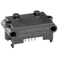
SDP600
Description
Digital Differential Pressure Sensor
Manufacturer
SENSIRION
Datasheet
1.SDP610.pdf
(10 pages)
Specifications of SDP600
Sensor Output
Voltage
Supply Current
6mA
External Depth
18mm
Voltage Rating
3.6V
Port Style
Tube
Pressure Measurement Type
Differential
Lead Free Status / RoHS Status
Lead free / RoHS Compliant


8. Instructions for Use
Standard wave soldering systems may be used for
soldering SDP600 series sensors. Reflow soldering is not
feasible and may damage the sensor.
The sensor ports must be protected from solder splash
and flux during soldering. Figure 6 shows an appropriate
temperature profile with maximum temperature values.
Figure 6: Suitable wave soldering profile.
The characteristics of wave soldering machines vary, so
any soldering setup must be tested before production use.
The sensors of the SDP600 series are designed to be
robust and vibration resistant. Nevertheless, the accuracy
of the high-precision SDP600 series can be degraded by
rough handling. Sensirion does not guarantee proper
operation in case of improper handling. Note: avoid
applying any mechanical stress to the solder joints of the
sensor during or as a result of PCB assembly.
The sensor ships in an antistatic package to prevent
electrostatic discharge (ESD), which can damage the part.
To avoid such damage, ground yourself using a grounding
strap or by touching a grounded object. Furthermore store
the parts in the antistatic package when not in use.
If necessary, the robustness of the sensor attachment to
the PCB can be increased by using a bracket as shown in
Figure 7.
Sensirion recommends using this additional bracket when
the sensor is fitted to a PCB. The bracket must be secured
before the pins are soldered to the PCB, as otherwise
sensor performance may be degraded by mechanical
stress.
www.sensirion.com
250°C
200°C
150°C
100°C
50°C
8.1
8.2
8.3
0°C
Start
Flux zone
Soldering instructions
Sensor handling
Additional attachment
Approx. PCB
bottom-side temp.
Entrance to solder
Preheat zone
Wave
PCB top-side
temperature
Exit from solder
Wave
(Time in wave < 2 s)
Solder Wave Peak
Temp. max. 260°C
Max 145°C
Approx.
1 min
Version 1.5 –January 2011
Figure 7: Supplementary bracket for the SDP600 series.
Due to the dynamic measurement principle, a small air
flow is required.
Figure 8: Typical air flow through the SDP6x0.
This air flow through the sensor creates a dependence on
the tube length. The error is less than 1% with a tube
length up to 1 m (with 3/16 inch inside diameter).
8.4
+120
-120
0
-600
Note: 1 sccm = 1 cm3/min at 0°C and 1013 mbar
(1 sccm = 0.001 standard liter).
Air flow and tubing
Pressure difference (Pa)
0
+600
8/10
Related parts for SDP600
Image
Part Number
Description
Manufacturer
Datasheet
Request
R


Part Number:
Description:
MODULE SENSOR TEMP+HUMIDITY
Manufacturer:
Parallax Inc
Datasheet:

Part Number:
Description:
Humidity Sensor Filter Cap
Manufacturer:
SENSIRION
Datasheet:

Part Number:
Description:
Sensor Evaluation Kit
Manufacturer:
SENSIRION
Datasheet:

Part Number:
Description:
Sensor Evaluation Kit
Manufacturer:
SENSIRION
Datasheet:
Part Number:
Description:
Sensor Evaluation Kit
Manufacturer:
SENSIRION
Datasheet:
Part Number:
Description:
Sensor Evaluation Kit
Manufacturer:
SENSIRION
Datasheet:


Part Number:
Description:
SENSOR, MASS FLOW
Manufacturer:
SENSIRION
Datasheet: