PS41-30-4MNB-C-FL18 Gems Sensors Inc, PS41-30-4MNB-C-FL18 Datasheet - Page 2
PS41-30-4MNB-C-FL18
Manufacturer Part Number
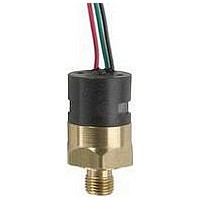
PS41-30-4MNB-C-FL18
Description
Pressure Switch
Manufacturer
Gems Sensors Inc
Datasheet
1.PS41-10-4MNB-C-HC.pdf
(2 pages)
Specifications of PS41-30-4MNB-C-FL18
Contact Voltage Ac Max
250V
Circuitry
SPDT
Operating Pressure Max
100psi
Port Style
NPT
Contact Current Ac Max
5A
Contact Current Max
5A
Contact Voltage Dc Max
28V
Switch Terminals
Wire Leaded
Connection Size
1/4"
Contact Current Dc Max
5A


How To Order
Use the Bold characters from the chart below to construct a product code. Please reference Notes.
1 Pressure Range Code
2 Pressure Fitting
3 Circuit
4 Electrical Termination
Table 1 — Pressure Range Codes
** These numbers are for the standard microswitch. With either the -SP or -10A option, the values are typically 20% greater than those
* Repeatability and set point of units may change due to the effects of temperature.
Pressure Range Code
Brass
316 Stainless Steel
-CABXX = 18 AWG PVC Cable
listed. With the -RD option, the values will be typically 25% less than those listed. In certain applications deadband can be tailored
and controlled to customer specifications. Consult factory for details.
-FLSXX = Flying Leads w/PVC Shrink Tubing
-2MNB = 1/8˝ NPTM
-4MNB = 1/4˝ NPTM
-2MGB = 1/8˝ BSPM (G type)
-4MGB = 1/4˝ BSPM (G type)
-2MNS = 1/8˝ NPTM
-4MNS = 1/4˝ NPTM
-4MGS = 1/4˝ BSPM (G type)
-4MSB = 7/16˝-20 SAE Male
-6MSB = 9/16˝-18 SAE Male
-4MSS = 7/16˝-20 SAE Male
-FLXX = Flying Leads
-ELXX = 1/2˝ NPT Male Conduit w/Flying Leads
Insert Pressure Range Code from Table 1, below.
-HCR = Right Angle DIN 43650A 9mm Cable
-HNR = Right Angle DIN 43650A with 1/2˝ Female
-HR = Right Angle DIN 43650A Male Half Only
-HN = DIN 43650A with 1/2˝ Female NPT Conduit
-HC = DIN 43650A 9mm Cable Clamp
-SP = Spade Terminals
-A = SPST/N.O.
-B = SPST/N.C.
-C = SPDT
-H = DIN 43650A Male Half Only
10
20
30
Clamp
NPT Conduit
6
1
3
6
2
PS41 -10 -4MNB -C -H
5
3.5-8 psi (0.24-0.55 bar)
7-30 psi (0.48-2.07 bar)
25-100 psi (1.7-6.9 bar)
Pressure Range
6
6
Visit www.GemsSensors.com for most current information.
3
1
4
6
6
5 Options
6 Fixed Set Point (optional)
2
-OXY = Oxygen Cleaned
A. Specify set point -FS
B. Set Point Actuation
-WM = Weather Pack Connector, Male
-10A = 10A @ 125/250 VAC Max. Rating
-WF = Weather Pack Connector, Female
-RD = Reduced Differential
-DE = Deutsch Connector, Male, DT04 Series
-IP = Ingress Protection
(in PSI or BAR, see example)
R on Rising Pressure
F on Falling Pressure
Example: -FS0.5BARF for 0.5 BAR Falling
or -FS5PSIR for 5 PSI Rising
-N = Neoprene Diaphragm
-G = Gold Contacts
-V = Viton
-E = EPDM Diaphragm
±0.35 psi (0.024 bar) +2% of setting
±0.8 psi (0.055 bar) +2% of setting
±2.0 psi (0.138 bar) +2% of setting
7
(for loads less than 12 mA @ 12 VDC)
(25% reduction typical)
3
®
Repeatability*
Diaphragm
4
8
-XX -XXXX
5
9
1.50 psi (0.14 bar) +7% of setting
6
5 psig (0.28 bar) +10% of setting
3 psi (0.21 bar) +8% of setting
Average Deadband**
Notes:
1. Other fittings available.
2. Requires -10A or -G option.
3. 18˝ is standard. Specify lead
4. 18˝ is standard. Specify lead
5. 36˝ is minimum. Specify
6. DIN connectors require -C
7. Options -10A, -G or -RD
8. Ingress Protection is
9. Set Point must be within
Consult factory.
(20% increase in deadband
typical)
length in inches (max. 48˝).
e.g. -FL18 or -FLS30.
length in inches (max. 48˝).
e.g. -EL18 or -EL30.
cable length in inches. e.g.
-CAB36 or -CAB120.
SPDT circuit.
cannot be combined.
available only with -FL, -FLS
or -CAB Electrical
Termination choices.
Ingress Protection requires
Fixed Set Point -FS.
Pressure Range selected in
Step 1.
mInIaTURE
I-10
Related parts for PS41-30-4MNB-C-FL18
Image
Part Number
Description
Manufacturer
Datasheet
Request
R

Part Number:
Description:
Pressure Switch
Manufacturer:
Gems Sensors Inc
Datasheet:

Part Number:
Description:
MINI PRESSURE SWITCH 5-30 PSI 1/4" BSPM PRESSURE FITTING
Manufacturer:
Gems Sensors Inc
Part Number:
Description:
FLOAT LEVEL MULTI STAINLESS SENSORS
Manufacturer:
Gems Sensors Inc
Part Number:
Description:
LS-77700 316 Stainless Steel ,Buna-N, 20 VA, .84 Sp.Gr.
Manufacturer:
Gems Sensors Inc

Part Number:
Description:
LIQUID LEVEL SENSOR
Manufacturer:
Gems Sensors Inc
Datasheet:
Part Number:
Description:
LS-77700 316 Stainless Steel ,Buna-N, 20 VA, .84 Sp.Gr.
Manufacturer:
Gems Sensors Inc