Q60BB6LAF1400Q BANNER ENGINEERING, Q60BB6LAF1400Q Datasheet - Page 2
Q60BB6LAF1400Q
Manufacturer Part Number
Q60BB6LAF1400Q
Description
Photoelectric Sensor
Manufacturer
BANNER ENGINEERING
Type
Adjustable Fieldr
Specifications of Q60BB6LAF1400Q
Output Current
150mA
Sensor Output
NPN/PNP
Supply Voltage Range Dc
10V To 30V
Leaded Process Compatible
No
Peak Reflow Compatible (260 C)
No
Sensor Input
Laser
Brand/series
Q60LAF
Current, Switching
150 mA
Function
Proximity
Ip Rating
IP67
Output
NPN/PNP
Primary Type
Photoelectric
Range, Measurement
1400 mm
Sensing Mode
Adjustable Field
Technology
Photoelectric
Termination
5-Wire Connector
Voltage, Supply
30 VDC
Accessories Available
Cordsets and Brackets
Lead Free Status / Rohs Status
RoHS Exempt Product


Q60LAF Series Laser Adjustable-Field Sensors
The Q60LAF sensor is a full-featured adjustable-field sensor. These adjustable-
field sensors are able to detect objects of relatively low reflectivity, while ignoring
other objects in the background (beyond the cutoff point). The cutoff distance is
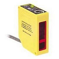
mechanically adjustable, using the 2-turn adjustment screw (Figure 1). A rotating
pointer indicates the relative cutoff position. (The indicator moves clockwise to show
increasing distance.) The collimated laser emitter produces a small, bright spot,
allowing easy alignment and precision sensing of relatively small objects at long
range.
Two push buttons (ON Delay and OFF Delay) are used to set the output delay options,
to toggle between light and dark operate modes and to lock out the push buttons for
security purposes. For 10 to 30V dc models, these functions also may be accomplished
using the remote wire.
Seven LED indicators show, during RUN mode, the sensor configuration and
operating status. During Delay Configuration, 5 of the LEDs combine to form a single
light bar that indicates relative ON or OFF delay time.
Adjustable-Field Sensing – Theory of Operation
In operation, the Q60LAF compares the reflections of its emitted light beam (E) from
an object back to the sensor’s two differently-aimed detectors R1 and R2 (see
Figure 2). If the near detector (R1) light signal is stronger than the far detector (R2)
light signal (see object A, closer than the cutoff distance), the sensor responds to the
object. If the far detector (R2) light signal is stronger than the near detector (R1) light
signal (see object B, object beyond the cutoff distance), the sensor ignores the object.
The cutoff distance for Q60LAF sensors is adjustable from 200 to 1400 mm
(8" to 55") for Class 1 laser models, and 200 to 2000 mm (8" to 80") for Class 2 laser
models. Objects lying beyond the cutoff distance are ignored.
In the drawings and discussion on this page and page 4, the letters E, R1, and R2
identify how the sensor’s three optical elements (Emitter “E”, Near Detector “R1”,
and Far Detector “R2”) line up across the face of the sensor. The location of these
elements defines the sensing axis (see Figure 3). The sensing axis becomes important
in certain situations, such as those illustrated in Figures 7 and 8.
2
P/N 114348
Overview
Banner Engineering Corp.
www.bannerengineering.com • Tel: 763.544.3164
Figure 3. Q60 sensing axis
Figure 1. Q60LAF features
Figure 2. Adjustable field sensing concept
Detector
Detector
When an object approaches from the side, the most reliable
sensing usually occurs when the line of approach is parallel
to the sensing axis.
�����������������������
�����������������������
����������������������
���������������������
Near
�������������������
Far
Receiver
Elements
Sensing
����������������
�����������������
R1
R2
Axis
E
�������������
������������
������������
��������
��������
Lenses
������������
������������
��������������
•
Minneapolis MN, U.S.A.
Object
A
Sensing
Range
Receiver
Elements
Emitter
Distance
Cutoff
���
��
��
������
����������
�����
�����
Background
Object B
���
�����
�����
��
�
–
or
Related parts for Q60BB6LAF1400Q
Image
Part Number
Description
Manufacturer
Datasheet
Request
R

Part Number:
Description:
Photoelectric Sensor
Manufacturer:
BANNER ENGINEERING
Datasheet:

Part Number:
Description:
Photoelectric Sensor
Manufacturer:
BANNER ENGINEERING
Datasheet:

Part Number:
Description:
LEDIR70XD4-XM-81039 MAX INTENS STROBE ONLY NO BANNER MARKS
Manufacturer:
BANNER ENGINEERING
Part Number:
Description:
M18SP6DL-72225 LABELED MOELLER NO BANNER MARKINGS BULK PACK
Manufacturer:
BANNER ENGINEERING
Part Number:
Description:
M18SP6DLQ-72226 LABLED MOELLER NO BANNER MARKINGS BULK PACK
Manufacturer:
BANNER ENGINEERING
Part Number:
Description:
M18SP6L-72223 LABELED MOELLER NO BANNER MARKINGS BULK PACK
Manufacturer:
BANNER ENGINEERING
Part Number:
Description:
M18SP6LQ-72224 LABELED MOELLER NO BANNER MARKINGS BULK PACK
Manufacturer:
BANNER ENGINEERING
Part Number:
Description:
P4D1-77908 P4 DRIVER GENERIC NO BANNER MARKINGS RESALE TO CUSTOMER
Manufacturer:
BANNER ENGINEERING
Part Number:
Description:
Photoelectric Sensor
Manufacturer:
BANNER ENGINEERING
Datasheet:

Part Number:
Description:
Programmable Indicator Light
Manufacturer:
BANNER ENGINEERING
Datasheet:
Part Number:
Description:
INDICATOR LED PANEL 50MM GRN/RED/YEL 30V
Manufacturer:
BANNER ENGINEERING
Datasheet:
Part Number:
Description:
Programmable Indicator Light
Manufacturer:
BANNER ENGINEERING
Datasheet: