Q45BW22LV BANNER ENGINEERING, Q45BW22LV Datasheet - Page 7
Q45BW22LV
Manufacturer Part Number
Q45BW22LV
Description
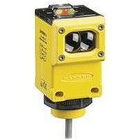
Photoelectric Sensor
Manufacturer
BANNER ENGINEERING
Datasheet
1.Q45BW22LVQ.pdf
(12 pages)
Specifications of Q45BW22LV
Output Current
300mA
Sensor Output
Relay
Peak Reflow Compatible (260 C)
No
Sensing Range Min
0.08m
Sensor Input
Optical
Supply Voltage Max
250VAC
Sensing Range Max
9mm
Leaded Process Compatible
No


Supply Voltage and Current
Output Configuration
Output Rating
Output Protection Circuitry
Output Response Time
Repeatability
Adjustments
Indicators
Construction
Environmental Rating
Connections
Operating Conditions
Application Notes
Certifications
Supply Protection Circuitry
Banner Engineering Corp.
www.bannerengineering.com • Tel: 763.544.3164
•
Minneapolis, MN U.S.A.
90 to 250V ac (50 - 60 Hz). Average current 20 mA. Peak current 500 mA at 120C ac, 750 mA at 250V ac
Protected against transient voltages.
Short circuit/overload protected FET solid-state relay
Continuous current: 300 mA max. to 50° C (derate to 200 mA at 70°C, 5 mA/°C)
Inrush current: 3A max. for 100 milliseconds, 5A max. for 1 millisecond
Off-state leakage current: <100 microamps
Saturation voltage: <3V at 200 mA
Manually-resettable output latch-out trips in the event of an output overload or short circuit condition. The
green Power LED flashes to indicate the latch-out. To reset the output, remove power to the sensor and load
for 5 seconds, then restore power.
Opposed mode: 2 milliseconds ON, 1 millisecond OFF
All other sensing modes: 2 milliseconds ON/OFF
(NOTE: 100 millisecond delay on power-up. Output is non-conducting during this time.)
Opposed mode: 0.25 milliseconds
All other sensing modes: 0.5 milliseconds
Response time and repeatability specifications are independent of signal strength.
Beneath sensor’s transparent cover: Light/Dark Operate select switch; and multi-turn Sensitivity control
(allows precise sensitivity setting – turn clockwise to increase gain). Optional logic and logic/display
modules have adjustable timing functions (see page 10).
Indicator LEDs are clearly visible beneath a raised transparent Lexan
Power (green) LED lights whenever 90 to 250V ac power is applied, and flashes to indicate output overload
Signal (red) AID™ System LED lights whenever the sensor sees its modulated light source, and pulses at a
Load (yellow) LED lights whenever the output relay is energized
Optional 7-element LED signal strength display module
Molded reinforced thermoplastic polyester housing, o-ring-sealed transparent Lexan
lenses, and stainless steel hardware. Q45s are designed to withstand 1200 psi washdown. The base of
cabled models has a 1/2" NPS integral internal conduit thread.
NEMA 6P, IEC IP67
PVC-jacketed 2 m (6.5') or 9 m (30') cables, or 3-pin Mini-style (“Q” suffix models) or 4-pin Micro-style
(“Q1” suffix models) quick-disconnect (QD) fittings are available. QD cables are ordered separately.
See page 10.
Temperature: -40° to +70° C (-40° to +158°F)
Maximum relative humidity: 90% at 50°C (non-condensing)
Optional output timing modules are available. See page 10 for more information.
Lexan
®
is a registered trademark of General Electric Co.
Q45BW22 Series Specifications
or output short circuit
R
rate proportional to the strength of the received light signal
®
dome on top of the sensor.
Q45BW22 Series
®
cover, molded acrylic
page
7
Related parts for Q45BW22LV
Image
Part Number
Description
Manufacturer
Datasheet
Request
R

Part Number:
Description:
Photoelectric Sensor
Manufacturer:
BANNER ENGINEERING
Datasheet:

Part Number:
Description:
Photoelectric Sensor
Manufacturer:
BANNER ENGINEERING
Datasheet:

Part Number:
Description:
LEDIR70XD4-XM-81039 MAX INTENS STROBE ONLY NO BANNER MARKS
Manufacturer:
BANNER ENGINEERING
Part Number:
Description:
M18SP6DL-72225 LABELED MOELLER NO BANNER MARKINGS BULK PACK
Manufacturer:
BANNER ENGINEERING
Part Number:
Description:
M18SP6DLQ-72226 LABLED MOELLER NO BANNER MARKINGS BULK PACK
Manufacturer:
BANNER ENGINEERING
Part Number:
Description:
M18SP6L-72223 LABELED MOELLER NO BANNER MARKINGS BULK PACK
Manufacturer:
BANNER ENGINEERING
Part Number:
Description:
M18SP6LQ-72224 LABELED MOELLER NO BANNER MARKINGS BULK PACK
Manufacturer:
BANNER ENGINEERING
Part Number:
Description:
P4D1-77908 P4 DRIVER GENERIC NO BANNER MARKINGS RESALE TO CUSTOMER
Manufacturer:
BANNER ENGINEERING
Part Number:
Description:
Photoelectric Sensor
Manufacturer:
BANNER ENGINEERING
Datasheet:

Part Number:
Description:
Programmable Indicator Light
Manufacturer:
BANNER ENGINEERING
Datasheet:
Part Number:
Description:
INDICATOR LED PANEL 50MM GRN/RED/YEL 30V
Manufacturer:
BANNER ENGINEERING
Datasheet:
Part Number:
Description:
Programmable Indicator Light
Manufacturer:
BANNER ENGINEERING
Datasheet: