EO60-Q08-RN6X BANNER ENGINEERING, EO60-Q08-RN6X Datasheet - Page 6
EO60-Q08-RN6X
Manufacturer Part Number
EO60-Q08-RN6X
Description
PHOTO SENSOR RECEIVER
Manufacturer
BANNER ENGINEERING
Datasheet
1.EO60-Q08-RN6X.pdf
(7 pages)
Specifications of EO60-Q08-RN6X
Peak Reflow Compatible (260 C)
No
Rise Time
1ms
Leaded Process Compatible
No
Opto Case Style
Module
Supply Current
30mA
Operating Temperature Range
0°C To +50°C
Supply Voltage Range
10V To 30V


Q08 Series Opposed-Mode Sensors
Banner model Q08 emitters and receivers are very small, rugged, and
powerful infrared opposed-mode (“through-beam”) sensor pairs contained
within die-cast metal housings only 8-mm deep . Sensing range is 20". Q08
emitters and receivers are totally self-contained and are powered from 10 to
30V dc.
Q08 opposed sensor pairs are ideal for sensing of parts on small conveyors
and for other similar short-range opposed-mode sensing uses. The size of
these powerful compact sensors makes them especially useful in
applications with limited space.
A synchronizing wire connecting the emitter and receiver “gates” the
receiver to look for a light signal only during the instant when the emitter
sends a light pulse from its infrared LED. This produces exceptionally high
immunity to electrical noise and false signals. The modulated infrared
sensing beam, along with polysulfone lenses on both the emitter and
receiver, result in extremely high immunity to interference from visible
ambient light.
Model Q08 receivers have a solid-state output capable of switching loads
of up to 150 mA dc, continuous. Four output types are offered:
NPN sinking/light operate, NPN sinking/dark operate, PNP sourcing/light operate, and
PNP sourcing/dark operate. See the table of available models on page 1. A light-
operate output conducts when the receiver sees the emitter’s pulse-synchronized light
source. A dark-operate output conducts when the receiver does not see the emitter’s
pulse-synchronized light source.
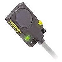
A green LED indicator on both the emitter and receiver units, visible from the front and
left side of the sensor, lights whenever dc power is applied (see figure 1). A yellow LED
(receiver units only), visible from the front and the right side of the receiver, lights
whenever the receiver’s output circuit is conducting.
Figure 2. Q08 Opposed-Mode Sensor dimensions (attached cable version only)
Clearwater Tech - Phone: 800.894.0412 - Fax: 208.368.0415 - Web: www.clrwtr.com - Email: info@clrwtr.com
#4 (M3) Screw Clearance
20.0 mm (0.79")
ø 3.40 mm (0.134")
13.00 mm (0.512")
(2 Holes)
8.0 mm (0.32")
Q08 Series Opposed-Mode Sensor Overview
2 m (6.5') Cable
9.0 mm
(0.35")
3.00 mm (0.12")
32.0 mm
(1.26")
Beam emits
from mechanical center
of lens
Figure 1. Q08 Series Opposed-Mode emitter and
receiver features
Related parts for EO60-Q08-RN6X
Image
Part Number
Description
Manufacturer
Datasheet
Request
R

Part Number:
Description:
Photoelectric Sensor
Manufacturer:
BANNER ENGINEERING
Datasheet:

Part Number:
Description:
Photoelectric Sensor
Manufacturer:
BANNER ENGINEERING
Datasheet:

Part Number:
Description:
LEDIR70XD4-XM-81039 MAX INTENS STROBE ONLY NO BANNER MARKS
Manufacturer:
BANNER ENGINEERING
Part Number:
Description:
M18SP6DL-72225 LABELED MOELLER NO BANNER MARKINGS BULK PACK
Manufacturer:
BANNER ENGINEERING
Part Number:
Description:
M18SP6DLQ-72226 LABLED MOELLER NO BANNER MARKINGS BULK PACK
Manufacturer:
BANNER ENGINEERING
Part Number:
Description:
M18SP6L-72223 LABELED MOELLER NO BANNER MARKINGS BULK PACK
Manufacturer:
BANNER ENGINEERING
Part Number:
Description:
M18SP6LQ-72224 LABELED MOELLER NO BANNER MARKINGS BULK PACK
Manufacturer:
BANNER ENGINEERING
Part Number:
Description:
Photoelectric Sensor
Manufacturer:
BANNER ENGINEERING
Datasheet:

Part Number:
Description:
Programmable Indicator Light
Manufacturer:
BANNER ENGINEERING
Datasheet:
Part Number:
Description:
INDICATOR LED PANEL 50MM GRN/RED/YEL 30V
Manufacturer:
BANNER ENGINEERING
Datasheet:
Part Number:
Description:
Programmable Indicator Light
Manufacturer:
BANNER ENGINEERING
Datasheet: