E3SRS30E42-30 Omron, E3SRS30E42-30 Datasheet - Page 6
E3SRS30E42-30
Manufacturer Part Number
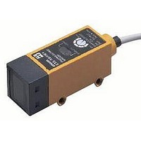
E3SRS30E42-30
Description
Photoelectric Sensor
Manufacturer
Omron
Datasheet
1.E3SRS30E42-30.pdf
(11 pages)
Specifications of E3SRS30E42-30
Sensing Range
300mm
Output Current
80mA
Sensor Output
NPN
Supply Voltage Range Dc
12V To 24V
Supply Voltage Max
24VDC
Sensing Range Max
300mm
Switch Terminals
Cable
Sensing Mode
Retroreflective
Lead Free Status / RoHS Status
Lead free / RoHS Compliant


PNP Output
Plug (Sensor I/O Connector)
*1. Reverse the polarity of the power supply to change the output mode of the E3S-R.
*2. Voltage output (When connecting a transistor circuit, etc.)
E3S-R31
E3S-R36
E3S-R81
E3S-R86
E3S-RS30E4(42)
E3S-R1E4(42)
1
Model
2
4
3
Model
Terminal No.
1
2
3
4
Operation
Light-ON
Dark-ON
mode
Operation
Light-ON
Dark-ON
XS2F-D421-DC0-A
mode
Light indicator
(Red)
Output
transistor
Load
(e.g., relay)
Light indicator
(Red)
Output
transistor
Load
(e.g., relay)
No incident light
No incident light
Light indicator
(Red)
Output
transistor
Load 1
(e.g., relay)
Load 2
Light indicator
(Red)
Output
transistor
Load 1
(e.g., relay)
Load 2
Incident light
Incident light
Timing Charts
No incident light
No incident light
Operate
Operate
Incident light
Incident light
Reset
Reset
OFF
OFF
OFF
OFF
ON
ON
ON
ON
Timing Charts
Operate
Operate
Reset
Reset
OFF
OFF
OFF
OFF
and black leads)
and black leads)
ON
ON
(Between blue
(Between blue
ON
ON
H
H
L
(Between brown and black leads)
L
(Between brown and black leads)
(Between blue and black leads)
(Between blue and black leads)
Brown
Blue
Black
Note: Pin 2 is not used.
sifica-
Clas-
tion
DC
Operation selector
(LIGHT ON)
(DARK ON)
D side
L side
Wire color
Brown cable:
+V
Blue cable:
0 V
Brown cable:
0 V
Blue cable:
+V
Connection
Brown
Black
Blue
Cable
---
Connection
Light
indicator
pin No.
Light
indicator
1
2
3
4
(Red)
(Red)
(Green)
(Green)
Power supply (0 V)
Power supply (+V)
Stability
indicator
Stability
indicator
Application
Connector Pin Arrangement
Photo-
electric
Sensor
Main
Circuit
Photo-
electric
Sensor
main
circuit
Output
Note: Pin 2 is not used.
---
Output circuit
Output circuit
2
100 mA max.
1
3
1.5 to
4 mA
4
Z
Refer to Introduction
to Sensor I/O
connectors for
details.
D
1
4
3
Brown
Black
Blue
Load
(relay)
Brown *1
Black
Blue *1
E3S-R
Load 1
Load 2
(relay)
24 VDC
80 mA max.
1.5 to 4 mA
10 to
30 VDC
12 to
0 V
*2
6
Related parts for E3SRS30E42-30
Image
Part Number
Description
Manufacturer
Datasheet
Request
R

Part Number:
Description:
G6S-2GLow Signal Relay
Manufacturer:
Omron Corporation
Datasheet:
Part Number:
Description:
Compact, Low-cost, SSR Switching 5 to 20 A
Manufacturer:
Omron Corporation
Datasheet:
Part Number:
Description:
Manufacturer:
Omron Corporation
Datasheet:
Part Number:
Description:
Manufacturer:
Omron Corporation
Datasheet:
Part Number:
Description:
Manufacturer:
Omron Corporation
Datasheet:
Part Number:
Description:
Manufacturer:
Omron Corporation
Datasheet:
Part Number:
Description:
Manufacturer:
Omron Corporation
Datasheet:
Part Number:
Description:
Manufacturer:
Omron Corporation
Datasheet: