E3S-AR66 Omron, E3S-AR66 Datasheet - Page 7
E3S-AR66
Manufacturer Part Number
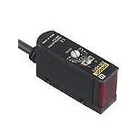
E3S-AR66
Description
Photoelectric Sensor
Manufacturer
Omron
Type
Photoelectric Sensorr
Series
E3S-Ar
Specifications of E3S-AR66
Output Current
100mA
Sensor Output
NPN
Supply Voltage Range Dc
10V To 30V
Sensing Range Max
2m
Sensor Housing
Rectangular
Mounting Type
Bracket
Switch Terminals
Connector
Output Type
Transistor
Features
Light ON / Dark ON
Height
21 mm
Length
51.3 mm
Maximum Operating Temperature
+ 55 C
Minimum Operating Temperature
- 25 C
Operating Supply Voltage
10 V to 30 V
Width
14.9 mm
Sensing Distance
2000 mm
Output Configuration
NPN
Sensor Input
Optical
Rohs Compliant
Yes
Sensing Method
Retroreflective
Sensing Object
Mirror
Sensing Light
Red
Current - Supply
30mA
Voltage - Supply
10 V ~ 30 V
Package / Case
Module, Connector
Lead Free Status / RoHS Status
Lead free / RoHS Compliant
Lead Free Status / RoHS Status
Lead free / RoHS Compliant, Lead free / RoHS Compliant


Structure of Sensor I/O Connector
E3S-AT21
E3S-AT71
E3S-AD21
E3S-AD71
E3S-AD22
E3S-AD72
E3S-AD23
E3S-AD73
E3S-AR21
E3S-AR71
1
Model
2
4
3
Terminal No.
1
2
3
4
Operation
Light-ON
Light-ON
Dark-ON
Dark-ON
mode
---
http://www.ia.omron.com/
XS2F-D421-DC0-A
Light indicator
(red)
Load
(e.g., relay)
Light indicator
(red)
Load
(e.g., relay)
Light indicator
(red)
Load
(e.g., relay)
Light indicator
(red)
Load
(e.g., relay)
Output
transistor
Output
transistor
Output
transistor
Emitter LED
Output
transistor
T: OFF-delay timer (0 to 100 ms)
No incident light
T: OFF-delay timer (0 to 100 ms)
No incident light
T: OFF-delay timer (0 to 100 ms)
No incident light
External
diagnostic
input
No incident light
T: OFF-delay timer (0 to 100 ms)
Indicator
(red)
Incident light
Incident light
Incident light
Incident light
Timing charts
Operate
Operate
Operate
Operate
Reset
Reset
Reset
Reset
OFF
OFF
OFF
OFF
OFF
OFF
OFF
OFF
OFF
OFF
OFF
ON
ON
ON
ON
ON
ON
ON
ON
ON
ON
ON
(Between brown and black)
(Between brown and black)
(Between brown and black)
(Between brown and black)
(Between blue and pink)
T
T
T
T
Brown
Black
Blue
L Side
(LIGHT ON)
D Side
(DARK ON)
L Side
(LIGHT ON)
D Side
(DARK ON)
selector
Note: Pin No. 2 is not used.
switch
Classification
Mode
---
For DC
Through-beam Receivers, Diffuse-reflective Sensors
Through-beam Emitters
Retro-reflective Sensors
Light
indica-
tor
(red)
Light
indica-
tor
(red)
(c)Copyright OMRON Corporation 2008 All Rights Reserved.
Wire color
Brown
Black
Blue
Stability
indicator
(green)
Stability
indicator
(green)
---
Photo-
electric
Sensor
main
circuit
Photo-
electric
Sensor
main
circuit
Power indicator
(red)
Photo-
electric
Sensor
main
circuit
Connection Pin No.
Output circuit
Z
Z
D
D
100 mA max.
100 mA max.
50 mA max.
50 mA max.
Z
Brown
Blue
Z
Pink
1
2
3
4
D
D
12 K
10 to 30 VDC
(External
diagnostic input)
Black
Black
Orange
Orange
Blue
Brown
Brown
Pink
Blue
(Control
output)
(Control
output)
(relay)
(relay)
Load
Load
0 V
(Self-diagnostic
output)
(Self-diagnostic
output)
(External
diagnostic input)
Application
(relay)
(relay)
Load
Load
E3S-A
Output
0 V
+V
---
10 to
30 VDC
10 to
30 VDC
7
Related parts for E3S-AR66
Image
Part Number
Description
Manufacturer
Datasheet
Request
R

Part Number:
Description:
E3S-AT66 RECEIVER
Manufacturer:
Omron
Datasheet:

Part Number:
Description:
E3S-AT61 RECEIVER
Manufacturer:
Omron
Datasheet:
Part Number:
Description:
E3S-AT66 Emitter
Manufacturer:
Omron
Datasheet:
Part Number:
Description:
EMITTER ONLY FOR E3S-AT16
Manufacturer:
Omron
Datasheet:
Part Number:
Description:
RECEIVER ONLY FOR E3S-AT16
Manufacturer:
Omron
Datasheet:
Part Number:
Description:
RECEIVER ONLY FOR E3S-AT11
Manufacturer:
Omron
Datasheet:
Part Number:
Description:
EMITTER ONLY FOR E3S-AT11
Manufacturer:
Omron
Datasheet:

Part Number:
Description:
OPTO SENSOR XMITTER/RCVR HORZ
Manufacturer:
Omron
Datasheet:
Part Number:
Description:
PHOTOELECTRIC
Manufacturer:
Omron
Datasheet:
Part Number:
Description:
PHOTOELECTRIC
Manufacturer:
Omron
Datasheet:

Part Number:
Description:
G6S-2GLow Signal Relay
Manufacturer:
Omron Corporation
Datasheet:
Part Number:
Description:
Compact, Low-cost, SSR Switching 5 to 20 A
Manufacturer:
Omron Corporation
Datasheet:
Part Number:
Description:
Manufacturer:
Omron Corporation
Datasheet: