CX-21 PANASONIC EW, CX-21 Datasheet - Page 6
CX-21
Manufacturer Part Number
CX-21
Description
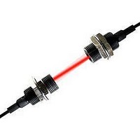
PHOLOELECTRIC SENSOR
Manufacturer
PANASONIC EW
Datasheet
1.CX-21.pdf
(14 pages)
Specifications of CX-21
Output Current
100mA
Sensor Output
NPN Open Collector
Supply Voltage Range Dc
12V To 24V
Lead Free Status / RoHS Status
Lead free / RoHS Compliant
Available stocks
Company
Part Number
Manufacturer
Quantity
Price
Company:

Part Number:
CX-21
Manufacturer:
Coilcraft
Quantity:
8 500


I/O CIRCUIT AND WIRING DIAGRAMS
I/O circuit diagram
Notes: 1) The emitter of the thru-beam type sensor does not incorporate
Notes:
Notes:
I/O circuit diagram
Notes: 1) The emitter of the thru-beam type sensor does not incorporate
Notes:
SENSING CHARACTERISTICS (TYPICAL)
Correlation between setting distance and excess gain
100
Symbols ... D: Reverse supply polarity protection diode
Symbols ... D: Reverse supply polarity protection diode
50
10
1
5
NPN output type
PNP output type
0
All models
2) Only CX- S incorporates the self-diagnosis output.
3) The plug-in connector type sensor does not incorporate the
2) When connecting the mating cable to the plug-in connector type
Z
Internal circuit
Internal circuit
Tr
D2
Tr
the sensing output.
self-diagnosis output. When connecting the mating cable, the
white wire is not connected.
the sensing output.
sensor, the white wire is not connected.
5
2
Setting distance L (m)
Tr
Z
T
Z
Tr : PNP output transistor
D
D
D1
r1
D
1
: Surge absorption zener diode
, T
10
, Z
CX-23
r2
Z
D2
: NPN output transistor
D
Z
: Surge absorption zener diode
D1
15
(Brown/1)
(Black/4)
Sensing output (Note 1)
(Orange/2)
Self-diagnosis output (Note 2, 3)
(Blue/3) 0V
(Brown/1)
(Black/4) Sensing
output (Note 1)
(Blue/3) 0V
CX-21
Users’ circuit
Users’ circuit
20
Color code/
Connector pin No. of the plug-in connector type
Color code/
Connector pin No. of the plug-in connector type
100mA max.
100mA max.
V
25
V
Load
Load
80mA max.
100
50
10
1
5
0
Load
1
Setting distance L (m)
2
CX-24
CX-22
12 to 24V DC
12 to 24V DC
10%
10%
CX-28IR
3
CX-29
4
5
Wiring diagram
Connector pin position
(Plug-in connector type)
Wiring diagram
Connector pin position
(Plug-in connector type)
Not connected
Not connected
2
2
1
1
V
V
Sensing output (Note 1)
Sensing output (Note 1)
0V
0V
3
3
Brown
Black (Note)
Blue
Brown
Black
Orange
Blue
4
4
Load
Load
Load
CX-20
12 to 24V DC
12 to 24V DC
10%
10%
165
Related parts for CX-21
Image
Part Number
Description
Manufacturer
Datasheet
Request
R

Part Number:
Description:
2-50mm, 2%Hys BGS/FGS, NPN, 2m Cable, 6.5mm Spot
Manufacturer:
PANASONIC EW

Part Number:
Description:
2-50mm, 2%Hys BGS/FGS, PNP, 2m Cable, 6.5mm Spot
Manufacturer:
PANASONIC EW
Part Number:
Description:
2-50mm, 2%Hys BGS/FGS, M8 Connection PNP, 6.5mm Spot
Manufacturer:
PANASONIC EW
Part Number:
Description:
2-50mm, 2%Hys BGS/FGS, M8 Connection NPN, 6.5mm Spot
Manufacturer:
PANASONIC EW
Part Number:
Description:
15-100mm, 2%Hys BGS/FGS, PNP, 2m Cable
Manufacturer:
PANASONIC EW
Part Number:
Description:
15-100mm, 2%Hys BGS/FGS, M8 Connection PNP, 2m Cable
Manufacturer:
PANASONIC EW
Part Number:
Description:
15-100mm, 2%Hys BGS/FGS, M8 Connection NPN, 2m Cable
Manufacturer:
PANASONIC EW
Part Number:
Description:
POL RETRO 3M RED 12-24VDC NPN W/ RF-230(REPLACEMENT TO CX-29)
Manufacturer:
PANASONIC EW

Part Number:
Description:
SIGNAL RELAY, DPDT, 5VDC, 2A, PC BOARD
Manufacturer:
PANASONIC EW
Datasheet:


Part Number:
Description:
PHOTOMOS RELAY, 60VDC, 400mA
Manufacturer:
PANASONIC EW
Datasheet:

Part Number:
Description:
PHOTOMOS RELAY, 400V, 150mA
Manufacturer:
PANASONIC EW
Datasheet: