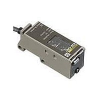
E3S-CR61 Omron, E3S-CR61 Datasheet

E3S-CR61
Specifications of E3S-CR61
Related parts for E3S-CR61
E3S-CR61 Summary of contents
Page 1
... Pre-wired 2 m 700 mm Pre-wired Connector (M12 700 mm Pre-wired 2 m 700 mm Pre-wired Connector (M12 CSM_E3S-C_DS_E_3_1 Red light Infrared light Model E3S-CT11 2M E3S-CT11-M1J 0. E3S-CT61 2M E3S-CT61-M1J 0.3M E3S-CR11 2M E3S-CR11-M1J 0. E3S-CR61 2M E3S-CR61-M1J 0.3M E3S-CD11 2M E3S-CD12 2M E3S-CD11-M1J 0.3M E3S-CD12-M1J 0.3M E3S-CD61 2M E3S-CD62 2M E3S-CD61-M1J 0.3M E3S-CD62-M1J 0.3M 1 ...
Page 2
... Note: For details on Sensor I/O Connectors and cables such as vibration-proof robot cables, refer to Introduction to Sensor I/O Connectors. Model Quantity 1 set each for Emitter and Re- E39-S61 ceiver (8 Slits total) Model Quantity E39-R1 1 Provided with the E3S-CR@1 (-M1J) Retro-reflective Sensor. E39-R2 1 E39-R3 1 E39-R4 1 E39-RS1 1 E39-RS2 1 Enables MSR function. ...
Page 3
... Sensors) *1. Refer to MSR function of Technical Guide (Technical version). *2. NEMA: National Electrical Manufactures Association Retro-reflective (with M.S.R. function) *1 Horizontal E3S-CR11(-M1J) E3S-CD11(-M1J) Vertical E3S-CR61(-M1J) E3S-CD61(-M1J) 700 (when using E39-R1) (300 white paper) Opaque, 75-mm dia. min. --- 20% max. of sensing distance ...
Page 4
... E3S-CR@1 (-M1J) + E39-R1 Reflector (Provided) 500 Reflector: E39-R1 300 100 Operating 1 level Distance (m) E3S-C Retro-reflective E3S-CR@1 (-M1J) + E39-R1 Reflector (Provided) 400 E39-R1 Reflector Y 300 X 200 100 Distance X (m) 100 200 300 400 Diffuse-reflective E3S-CD@@ (-M1J) 500 Sensing object: White paper 300 ...
Page 5
... Output transistor Operate Load (e.g. relay) Reset E3S-CT11(-M1J) E3S-CT61(-M1J) Incident light No incident light E3S-CR11(-M1J) Light indicator (Red) E3S-CR61(-M1J) Dark-ON Output transistor E3S-CD11(-M1J) Operate E3S-CD12(-M1J) Load (e.g. relay) Reset E3S-CD61(-M1J) E3S-CD62(-M1J) Through-beam Model Emitters ...
Page 6
... not possible to mount the E3S-C so that the sensing objects will be in the direction the mechanical axis, move the E3S-C upwards, downwards, to the left the right and secure the E3S the center of the range where the light indicator will be lit, at which time make sure that the stability indicator is lit ...
Page 7
... E3S-C was dipped in all the above oils at a temperature for 240 hours. 2. When using the E3S place where an oil other than the ones listed above is sprayed on the E3S-C, refer to the above kinematic viscosity and ph values. The location may be suitable for the E3S-C if ...
Page 8
... Dimensions Sensors Through-beam (Horizontal) E3S-CT11(-M1J) Emitter: E3S-CT@@-L Receiver: E3S-CT@@-D Lens (17 11) Optical axis 2 9 Two, M4 1.5 *1. The Mounting Bracket can be attached to side A. *2. The Emitters for Through-beam Sensors only have the power indicator (red). *3. The Emitter cable is 4-dia.vinyl-insulated round cable with 2 conductors (conductor cross section: 0.3 mm insulator diameter: 1 ...
Page 9
... Stability indicator (green) 4.2 9.2 8.3 4.2 Stainless steel (SUS304) 6.2 38.2 2 20.8 25.4 E3S-C Pre-wired Connector (-M1J) M12 1 4-dia. vinyl-insulated round cable with 3 conductors 2 (Conductor cross section: 0.2 mm (AWG24), Insulator diameter: 1.2 mm), Standard length 20.4 Mounting Holes Two 9.2 25 ...
Page 10
... Retro-/Diffuse-reflective (Vertical) E3S-CR61(-M1J) E3S-CD61(-M1J) E3S-CD62(-M1J) Optical axis Stability indicator (green) 7.2 Light indicator (red) 5.8 20 Two, M4 *The Mounting Bracket can be attached to side A. Accessories (Order Separately) Snap-in Long Slit (For Through-beam Models) E39-S61 6.5 20.1 Reflectors Refer to E39-L/F39-L/E39-S/E39-R for details. ...
Page 11
... Please read and understand this catalog before purchasing the products. Please consult your OMRON representative if you have any questions or comments. WARRANTY OMRON's exclusive warranty is that the products are free from defects in materials and workmanship for a period of one year (or other period if specified) from date of sale by OMRON. OMRON MAKES NO WARRANTY OR REPRESENTATION, EXPRESS OR IMPLIED, REGARDING NON-INFRINGEMENT, MERCHANTABILITY, OR FITNESS FOR PARTICULAR PURPOSE OF THE PRODUCTS ...


