SM312CV2 BANNER ENGINEERING, SM312CV2 Datasheet - Page 2
SM312CV2
Manufacturer Part Number
SM312CV2
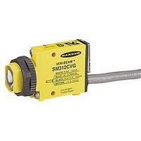
Description
Photoelectric Sensor
Manufacturer
BANNER ENGINEERING
Type
Convergentr
Specifications of SM312CV2
Output Current
150mA
Sensor Output
NPN/PNP
Supply Voltage Range Dc
10V To 30V
Sensor Input
Optical
Output Type
NPN/PNP, NO/NC
Supply Voltage Max
30VDC
Sensing Range Max
43mm
Contact Current Max
150mA
Brand/series
Mini-Beam®
Current, Switching
150 mA
Function
Proximity
Ip Rating
IP67
Light Immunity
Red
Light Source
LED
Mounting Type
Threaded
Output
NPN/PNP
Primary Type
Photoelectric
Range, Measurement
43 mm
Sensing Mode
Convergent
Standards
UL Recognized, CSA Certified, CE Marked
Technology
Photoelectric
Temperature, Operating
-20 to +70 °C
Termination
Cable
Voltage, Supply
30 VDC
Lead Free Status / Rohs Status
RoHS Exempt Product


MINI-BEAM
Proper operation of the SM312CV or SM312CV2 sensor requires that it be mounted
securely and aligned properly. In some applications, excessive movement or
vibration can result in intermittent or false operation caused by loss of alignment.
For best results, final-mount the sensor in an 18mm-hole by its threaded barrel or
use a mounting bracket (see page 6).
Begin with the sensor at the approximate position where it will be mounted. With
power applied to the circuit and with the sensor set for “light operate”, direct the
sensor’s visible red spot at the object approximately 16 mm (0.65 in) (for model
SM312CV) or 43 mm (1.7 in) (for model SM312CV2) directly in front of the lens.
Move the sensor very slightly toward or away from the object while observing the
red LED indicator on the back of the sensor. Note the near and far points at which
sensing occurs (the range of distance over which the LED remains lit). Mount the
sensor at a point approximately midway in the range. This should correspond to the
point at which the red sensing spot on the object appears most sharply defined on
the object surface. Mount the sensor at this position and distance.
* Note regarding Light/Dark operate switch:
page
• Turn switch fully clockwise for light operate (sensor outputs conduct when
• Turn switch fully counterclockwise for dark operate (sensor outputs conduct
sensing light is received)
when sensing light is not received)
2
®
Sensors
SM312CV and SM312CV2
MINI-BEAM Installation and Alignment
L o
w
Banner Engineering Corp.
www.bannerengineering.com • Tel: 763.544.3164
R e
f l e
light and pulses at a rate proportional to the
c t i
v i t
“AID” Indicator LED Lights when the
strength of the received light signal.
y B
sensor sees its own modulated
Distance from Sensor lens to object:
16 mm (0.65 in) for SM312CV
43 mm (1.7 in) for SM312CV2
a c
k g
CONVERGENT MODE ALIGNMENT
r o u
O b
j e c
n d
t
•
Minneapolis, U.S.A.
SM312CV2
SM312CV
or
15 Turn
Gain
Adjustment
and Light/Dark
Operate Switch*
L e
f t
Gasketed
Acrylic Cover
D o
U p
w n
R i
g h
t
Related parts for SM312CV2
Image
Part Number
Description
Manufacturer
Datasheet
Request
R

Part Number:
Description:
Photoelectric Sensor
Manufacturer:
BANNER ENGINEERING
Datasheet:

Part Number:
Description:
Photoelectric Sensor
Manufacturer:
BANNER ENGINEERING
Datasheet:

Part Number:
Description:
LEDIR70XD4-XM-81039 MAX INTENS STROBE ONLY NO BANNER MARKS
Manufacturer:
BANNER ENGINEERING
Part Number:
Description:
M18SP6DL-72225 LABELED MOELLER NO BANNER MARKINGS BULK PACK
Manufacturer:
BANNER ENGINEERING
Part Number:
Description:
M18SP6DLQ-72226 LABLED MOELLER NO BANNER MARKINGS BULK PACK
Manufacturer:
BANNER ENGINEERING
Part Number:
Description:
M18SP6L-72223 LABELED MOELLER NO BANNER MARKINGS BULK PACK
Manufacturer:
BANNER ENGINEERING
Part Number:
Description:
M18SP6LQ-72224 LABELED MOELLER NO BANNER MARKINGS BULK PACK
Manufacturer:
BANNER ENGINEERING
Part Number:
Description:
Photoelectric Sensor
Manufacturer:
BANNER ENGINEERING
Datasheet:

Part Number:
Description:
Programmable Indicator Light
Manufacturer:
BANNER ENGINEERING
Datasheet:
Part Number:
Description:
INDICATOR LED PANEL 50MM GRN/RED/YEL 30V
Manufacturer:
BANNER ENGINEERING
Datasheet:
Part Number:
Description:
Programmable Indicator Light
Manufacturer:
BANNER ENGINEERING
Datasheet: