SM2A31RL BANNER ENGINEERING, SM2A31RL Datasheet - Page 2
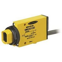
SM2A31RL
Manufacturer Part Number
SM2A31RL
Description
Photoelectric Sensor
Manufacturer
BANNER ENGINEERING
Type
Receiverr
Datasheet
1.SM2A31RL.pdf
(8 pages)
Specifications of SM2A31RL
Output Current
300mA
Sensor Output
SPST SCR
Peak Reflow Compatible (260 C)
No
Sensor Input
Laser
Circuitry
SPST
Sensing Range Max
30m
Leaded Process Compatible
No
Switch Terminals
Screw / Quick Connect
Primary Type
Photoelectric
Range, Measurement
30 m
Sensing Mode
Opposed
Technology
Photoelectric
Voltage, Supply
24-240 VAC


MINI-BEAM
Proper operation of the sensors requires that they be mounted
securely and aligned properly. Excessive movement or vibration
can cause intermittent or false operation due to loss of
alignment. For maximum mechanical stability, final-mount these
sensors in 18-mm holes by their threaded barrels or use a
mounting bracket (see page 6).
page
1) Begin with the emitter mounted securely in place. For
2) Set the receiver to light-operate mode. Apply power to the
3) Repeat the alignment motions after each GAIN reduction.
2
small-parts counting applications, stretch a string
between the emitter and receiver lenses to ensure that the
sensing beam will pass through the center of the sensing
location. For less critical applications, the receiver may be
initially positioned by line-of-sight placement. Mount the
receiver, leaving a means for movement.
emitter and receiver, and advance the receiver’s 15-turn
GAIN control to maximum (clockwise end of rotation).
The GAIN control is clutched at both ends to avoid
damage, and will “free-wheel” when either end point is
reached.
If the receiver is “seeing” the emitter’s light beam, the
receiver alignment LED should be “on”. Move the receiver
up-down-right-left (include angular rotation) to locate the
center of the movement range within which the LED stays
lit. Reducing the GAIN setting will restrict the range of
motion and allow precise positioning. NOTE: to aid
alignment at short ranges, it may help to further reduce
the strength of the light signal by temporarily masking the
emitter and/or receiver lens with tape or a sheet of paper.
When you have found the center of the movement range,
mount the receiver solidly in that position. Remove any
masking material, and increase the receiver GAIN to
maximum. Test the system by placing the object to be
detected into the sensing position. The receiver LED
indicator should go “off”. (If it does, alignment is
complete, and you may now switch the sensor to dark-
operate if the application requires it.) If the LED does not
go “off”, the cause is probably either “flooding” or “burn-
through”.
Flooding occurs when a portion of the effective beam
passes around the object to be sensed and activates the
receiver. Check that the object completely breaks the
beam, and that the beam is centered on the object. Add
apertures, if necessary, to tailor the effective beam to the
size or profile of the object being sensed. Burn-through
refers to a portion of the emitter’s light energy passing
through a thin or translucent object and activating the
receiver. Try sensing at a reduced GAIN setting or
consider an alternative sensing scheme.
®
Sensors
SMA31E/SM2A31R and SMA31EL/SM2A31RL
MINI-BEAM Installation and Alignment
* Note regarding Light/Dark operate switch:
• Turn switch fully clockwise for light operate (sensor
• Turn switch fully counterclockwise for dark operate
Emitter
outputs conduct when object is absent)
(sensor outputs conduct when object is present and
blocking light beam)
Receiver
sensor's output is conducting.
Red LED lights when the
Opposed Mode Alignment
Receiver
15 Turn
Gain
Adjustment
and Light/Dark
Operate Switch*
Gasketed
Acrylic Cover
L e
f t
D o
U p
w n
R i g
h t
Related parts for SM2A31RL
Image
Part Number
Description
Manufacturer
Datasheet
Request
R

Part Number:
Description:
Photoelectric Sensor
Manufacturer:
BANNER ENGINEERING
Datasheet:

Part Number:
Description:
Photoelectric Sensor
Manufacturer:
BANNER ENGINEERING
Datasheet:

Part Number:
Description:
LEDIR70XD4-XM-81039 MAX INTENS STROBE ONLY NO BANNER MARKS
Manufacturer:
BANNER ENGINEERING
Part Number:
Description:
M18SP6DL-72225 LABELED MOELLER NO BANNER MARKINGS BULK PACK
Manufacturer:
BANNER ENGINEERING
Part Number:
Description:
M18SP6DLQ-72226 LABLED MOELLER NO BANNER MARKINGS BULK PACK
Manufacturer:
BANNER ENGINEERING
Part Number:
Description:
M18SP6L-72223 LABELED MOELLER NO BANNER MARKINGS BULK PACK
Manufacturer:
BANNER ENGINEERING
Part Number:
Description:
M18SP6LQ-72224 LABELED MOELLER NO BANNER MARKINGS BULK PACK
Manufacturer:
BANNER ENGINEERING
Part Number:
Description:
P4D1-77908 P4 DRIVER GENERIC NO BANNER MARKINGS RESALE TO CUSTOMER
Manufacturer:
BANNER ENGINEERING
Part Number:
Description:
Photoelectric Sensor
Manufacturer:
BANNER ENGINEERING
Datasheet:

Part Number:
Description:
Programmable Indicator Light
Manufacturer:
BANNER ENGINEERING
Datasheet:
Part Number:
Description:
INDICATOR LED PANEL 50MM GRN/RED/YEL 30V
Manufacturer:
BANNER ENGINEERING
Datasheet:
Part Number:
Description:
Programmable Indicator Light
Manufacturer:
BANNER ENGINEERING
Datasheet: