QS18VP6AF100 BANNER ENGINEERING, QS18VP6AF100 Datasheet - Page 3
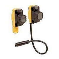
QS18VP6AF100
Manufacturer Part Number
QS18VP6AF100
Description
Photoelectric Sensor
Manufacturer
BANNER ENGINEERING
Type
Laserr
Specifications of QS18VP6AF100
Output Current
100mA
Sensor Output
PNP
Supply Voltage Range Dc
10V To 30V
Sensor Housing
Rectangular
Sensor Input
Optical
Output Type
Transistor
Sensing Range Max
100mm
Contact Current Max
100mA
Body Style
Rectangular
Brand/series
QS18 Series
Cable Type
6.5 in., 4-Wire
Construction
ABS Housing, Acrylic Lens Cover
Current Leakage
50 μA (Max.) @ 30 VDC
Current Rating
100 mA (Max.) @ 25 °C
Current, Switching
100 mA
Function
Proximity
Humidity
90% @ 50 °C
Includes
2.5 mm and 3 mm Mounting Hardware
Ip Rating
IP67
Light Source
LED
Output
PNP
Primary Type
Photoelectric
Range, Measurement
100 mm
Repeatability
175 μs
Response Time
0.2 μs
Sensing Mode
Adjustable Field
Standards
CE Marked
Technology
Photoelectric
Temperature, Operating
0 to +55 °C
Termination
Cable
Voltage, Saturation
1 V (Max.) @ 10 mA
Voltage, Supply
30 VDC
Lead Free Status / Rohs Status
RoHS Exempt Product


Figure 4. Set cutoff distance approximately
Banner Engineering Corp. • Minneapolis, MN U.S.A
www.bannerengineering.com • Tel: 763.544.3164
R1
R2
midway between the farthest target
and the closest background
E
Target
Distance
Cutoff
Background
WORLD-BEAM
Background Reflectivity and Placement
Avoid mirror-like backgrounds that produce specular reflections. False sensor re sponse will
occur if a back ground surface reflects the sensor’s light more strongly to the near detector
(R1) than to the far detector (R2). The result is a false ON condition (Figure 5). Use of a
diffusely-reflective (matte) background will cure this problem. Other possible solutions are to
angle either the sensor or the background (in any plane) so that the back ground does not
reflect light back to the sensor (see Figure 6). Position the background as far beyond the
cutoff distance as possible.
An object beyond the cutoff distance, either stationary (when po si tioned as shown in Figure
7) or if it moves past the face of the sensor in a direction perpendicular to the sensing axis,
can cause unwanted triggering of the sensor if it reflects more light to the near detector than
to the far detector. The problem is easily rem e died by rotating the sensor 90° (Figure 8).
The object then reflects the R1 and R2 fields equally, resulting in no false triggering. A better
solution, if possible, may be to reposition the object or the sensor.
Figure 5. Reflective background – problem
Figure 7. Object beyond cutoff – problem
A reflective background object in this position or
moving across the sensor face in this axis and
direction may cause false sensor response.
R1, R2,E
E
R1 = Near Detector
R2 = Far Detector
R2
R1
E
= Emitter
R2
R1
E
Core of
Emitted
Beam
Sensing
Field
Strong
Direct
Sensing
Reflection
to R1
Sensing
Field
Field
®
QS18 Adjustable-Field Sensors
Cutoff
Distance
Distance
Cutoff
Reflective
Background
R2
R1
E
Figure 8. Object beyond cutoff – solution
Figure 6. Reflective background – solution
A reflective background object in this position
or moving across the sensor face in this axis
will be ignored.
R1, R2,E
E
R1 = Near Detector
R2 = Far Detector
= Emitter
R2
R1
R2
R1
E
E
Core of
Emitted
Beam
Sensing
Sensing
Sensing
Field
Field
Strong
Direct
Reflection
Away From
Sensor
P/N 66981 rev. G
Distance
Cutoff
Cutoff
Distance
Reflective
Background
3
Related parts for QS18VP6AF100
Image
Part Number
Description
Manufacturer
Datasheet
Request
R

Part Number:
Description:
Photoelectric Sensor
Manufacturer:
BANNER ENGINEERING
Datasheet:

Part Number:
Description:
Photoelectric Sensor
Manufacturer:
BANNER ENGINEERING
Datasheet:

Part Number:
Description:
LEDIR70XD4-XM-81039 MAX INTENS STROBE ONLY NO BANNER MARKS
Manufacturer:
BANNER ENGINEERING
Part Number:
Description:
M18SP6DL-72225 LABELED MOELLER NO BANNER MARKINGS BULK PACK
Manufacturer:
BANNER ENGINEERING
Part Number:
Description:
M18SP6DLQ-72226 LABLED MOELLER NO BANNER MARKINGS BULK PACK
Manufacturer:
BANNER ENGINEERING
Part Number:
Description:
M18SP6L-72223 LABELED MOELLER NO BANNER MARKINGS BULK PACK
Manufacturer:
BANNER ENGINEERING
Part Number:
Description:
M18SP6LQ-72224 LABELED MOELLER NO BANNER MARKINGS BULK PACK
Manufacturer:
BANNER ENGINEERING
Part Number:
Description:
P4D1-77908 P4 DRIVER GENERIC NO BANNER MARKINGS RESALE TO CUSTOMER
Manufacturer:
BANNER ENGINEERING
Part Number:
Description:
Photoelectric Sensor
Manufacturer:
BANNER ENGINEERING
Datasheet:

Part Number:
Description:
Programmable Indicator Light
Manufacturer:
BANNER ENGINEERING
Datasheet:
Part Number:
Description:
INDICATOR LED PANEL 50MM GRN/RED/YEL 30V
Manufacturer:
BANNER ENGINEERING
Datasheet:
Part Number:
Description:
Programmable Indicator Light
Manufacturer:
BANNER ENGINEERING
Datasheet: